Ethernet is a computer network technology standard for LAN (Local area network). It was introduced commercially in 1989 and became IEEE Standard 802.3 in 1983. It has good backward compatibility and it runs at 10Mb, 100Mb or 1Gb per second. It can use a star topology (standard UTP cable) or a bus (old coaxial cable).
What is RJ45 ?
RJ45 connectors also known as 8P8C - (ISO 8877) are a kind of Unshielded Twisted Pair cables (UTP).
RJ45 Ethernet Cable UTP Wiring Diagram
There are two standards that are used for RJ45 connector wiring. They are EIA/TIA 568A and EIA/TIA 568B. They can also be known as T-568A and T-568B. Both standards can be used to make Ethernet UTP network cable. The cable could be a straig ht-through cable or a cross-over cable
WIRING DIAGRAM OF EIA/TIA 568A ETHERNET CABLE

Color codes of straight trought standard TIA/EIA 568 A :
- Pin 1 is White Green
- Pin 2 is Green
- Pin 3 is White orange
- Pin 4 is Blue
- Pin 5 is White Blue
- Pin 6 is Orange
- Pin 7 is White Brown
- Pin 8 is Brown
- Pin 1 is “TX+_D1†or Transmit Data+
- Pin 2 is “TX-_D1†or Transmit Data-
- Pin 3 is “RX+_D2†or Receive Data+
- Pin 4 is “BI+_D3†or Bi-directional+
- Pin 5 is “BI-_D3†or Bi-directional-
- Pin 6 is “RX-_D2†or Receive Data-
- Pin 7 is “BI+_D4†or Bi-directional+
- Pin 8 is “BI-_D4†or Bi-directional-
WIRING DIAGRAM OF EIA/TIA 568B ETHERNET CABLE
The pin description and names are the same as that for EIA/TIA 568A Ethernet cable. But the position of the different colored wires varies for both.
For optimal performance, a single cable has to be used for pins 1 and 2, pins 3 and 6, pins 4 and 5 and pins 7 and 8.

Color codes of straight trought standard TIA/EIA 568 B :
- Pin 1 is White orange
- Pin 2 is Orange
- Pin 3 is White Green
- Pin 4 is Blue
- Pin 5 is White Blue
- Pin 6 is Green
- Pin 7 is White Brown
- Pin 8 is Brown
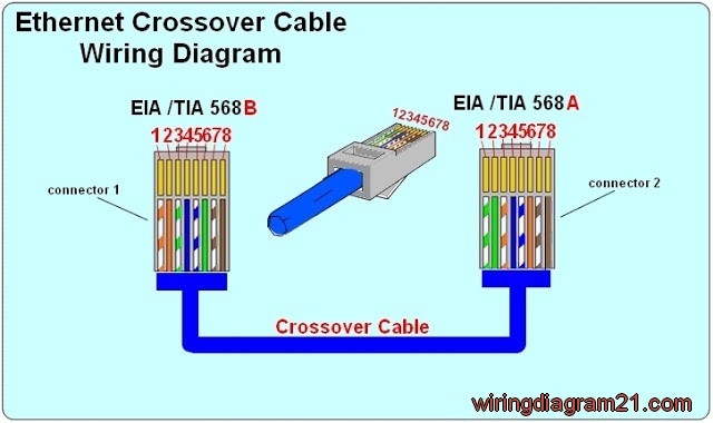
WIRING DIAGRAM OF ETHERNET CROSSOVER CABLE
A crossover cable contains a 568A specification at one end and a 568B specification at the other end.

Color codes of crossover cable :
& nbsp; Connector 1 Connector 2
& nbsp; Connector 1 Connector 2
- Pin 1 is White orange -------------------------------------------> Pin 1 is White Green
- Pin 2 is Orange -------------------------------------------> Pin 2 is Green
- Pin 3 is White Green -------------------------------------------> Pin 3 is White orange
- Pin 4 is Blue --------------------------------------------> Pin 4 is Blue
- Pin 5 is White Blue --------------------------------------------> < /b>Pin 5 is White Blue
- Pin 6 is Green --------------------------------------------> Pin 6 is Orange
- Pin 7 is White Brown ---------------------------------------------> Pin 7 is White Brown
- Pin 8 is Brown --------------------------------------------> Pin 8 is Brown
How To Crimp Rj45 cable :
Items needed to wire an Ethernet cable
- Crimper
- RJ 45 Connectors
- Bulk Cable
- Cable Tester
- Wire cutter
Steps for wiring an Ethernet cable
- Roll off the cable to the desired length plus a little extra and cut it.
- Strip the outer jacket of the cable using a stripper or a knife. You can strip of about 3 cm length. There are 8 wires that are twisted in 4 pairs. Each pair of wire has a wire of a distinct color. There will be another wire that is striped with the matching color of its partner. This wire is known as a tracer.
- Check the wires for any cut that is exposing the copper wire inside. If there is any like that, you might need to cut the wire and start again. If copper wire is exposed, it could lead to poor performance or cross talk.
- Untwist the pairs of wires and align them in the right order. You should refer to the diagram above to check the proper color orientation for each wiring standard. For a cross over cable one end is EIA/TIA 568B and the other end is EIA/TIA 568A.
- Keep the end of the wires flat and trim their ends leaving about 12.5 mm on length. Insert the wires into the RJ-45 plug while holding the connector or clip down. Ensure each wire is pushed deep and examine the connection again to confirm the arrangement.
- Hold the wire and place the plug into the crimping tool. You can also double crimp to ensure that the pins are properly set.
- All the steps above should be repeated for the other end of the cable.
- Now the Ethernet cable should be tested. You can test the connectivity from pin to pin or use a network cable tester.
Helpful Tips & Hints
- If the Ethernet cable does not work, check that the pins of both ends are connected. You can cut off the connector and repeat the steps above if not. Ensure that the connector is tightly crimped.
- The network cable length segment could be as long as 100m or even 150m in some cases. ‘
- Cat 5e cable is now the standard used instead of the Cat 5 standard. Cat 5e allows for longer distances and allows for far end cros stalk and better quality.
- For long cables, ensure that you test the cable before running it as this would save you a lot of stress.
- Ethernet cables should not be bent, stapled, stretched or deformed in any manner. Do not run them near noise inducing components and do not run them parallel with power cables.
No comments:
Post a Comment