Saturday, April 15, 2017

How To Wire Switch Controlled Outlet

Today i am gonna to guide you that how you can do wiring a switched outlet or how can you control a plug socket from a switch. In this post i will complete guide you with diagram and explanation. This wiring connection is very useful for safety because when you wire a switch with plug outlet then a person can easily off and on it.

How To Wire Switch Controlled Electrical Outlet


Requirements

Outlet : 1 Outlet / Plug Socket
Electric Supply : 220 volt / 110 volt
Switch : 1 Switch "switch type : one way switch
Screw drive


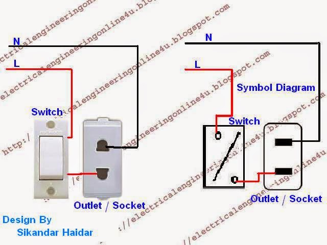
For doing this type of wiring in your home or Room, first of all switch off the main circuit breaker and then start your work. First of all connect the neutral (N) wire to outlet 1st terminal and then wire the Line wire (Phase) to switch first terminal and then connect a wire between 2nd te rminal of plug socket and one way switch 2nd terminal as shown in below diagram.

wiring a switched outlet diagram
Controlled an outlet from switch diagram

In above explanation diagram i shown on one side switch controlled outlet with image and on other side i shown it with symbol diagram. I hope this circuit help you very much for E learning, however there are some posts which help and guide you more
Also Read Below:
How to Wire Circuit Breaker?
How to Wir e Ceiling Fan?

Massage:

Now if you have any question regarding wiring a switched outlet and its diagram then you can tell me by writing a short massage in below comments section.

Thursday, April 13, 2017

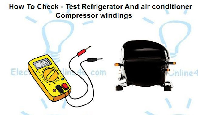
How To Check Compressor Windings With Multimeter

In this post you will learn about checking compressor windings or testing compressor windings. As you that in refrigerator or fridge compressor we have a electric induction motor which rotate the pump. In fridge compressor mostly in rated in single phase which have 3 terminals. i already publish a post about the start, run and common identification guide on this blog.
Some time when our refrigerator compressor stop working or not running problem then we must called a professional to test compressor or refrigerator. But if you want to check your compressor him self then this post is for you.


In this post i am telling you about some main and common reason of compressor not working and about testing compressor methods. There are many problems which we face in electrical refrigeration system and due which or refrigerator or Air conditioner stop working. But this post specially abo ut the check compressor motor winding.

checking compressor windings


Checking Compressor Windings Using Multi Meter

As you know that in single phase fridge or air conditioner compressor we have internally instill a single phase motor which consist two types of winding which we called main winding (ruining winding) and Auxiliary winding (starting winding). But if the compressor have receiving the power supply and still not working or running then may be its starting capacitor or relay is not working. But if you want to test compressor winding then follow the below steps.

Also Read Below
What is role of PTC Relay for fridge compressor?
Why we use overload protector with compressor?
How to find Out start, run and common in compressor terminals?
8 refrigeration not cooling problem and how to fix it?

First of all i want to gave an example of fridge compressor

If you want to check your fridge compressor then flow the below steps.


  • First of all plug out the fridge main electric plug. or switch of the supply which is connected to the fridge. 
  • Then see the relay and find our that which one terminal is common, start and run. The common terminal will be connect to overload protector or connect direct to electric supply wire. (note that direct wire was connected in those single phase compressor, in which the overload protector is instill inter nally).

  • After that find out the run terminal, in ptc relay the 2nd supply wire will connect direct to the run terminals of compressor, my means that the the 2nd wire which connect to relay point and that point supply goes to direct a terminal of compressor will be your run terminal.

  • Now you find out the common and run terminal of fridge compressor. So the other wire will be start terminal, otherwise 2nd supply wire will be connect to start terminal through a capacitor or heating resistor. (note that heating resistor is instill internally in ptc rely).

  • Now you find and marked your compressor terminal. Now set your multi meter knob on connectivity text or Ohm. Now connect one lead of meter to compressor common and other connect compressor un insulated body place. Continue this process with start and run terminal.

  • Now if you find our the connectivity of winding and body then its means that your compressor winding is short with compressor body or winding is uninsulated with iron core. And if have not connectivity between terminals and body. Then flow the next step.


  • The next step to test its resistance between one another. Test the compressor by unsung below method . So first read the below post, and flow the method to test the compressor.

How to identify compressor terminals?


  • Now if your compressor terminals reading shown same as in the above post then your compressor winding is not burn or if its shown different reading between common, start and run then your compressor winding is burn.


  • Now if compressor winding resistance shown same as i shown in the identifying compressor example then change your PTC (positive temperature coefficient thermistor) relay and com.. overload protector or capacitor and if still not working then call a professional.


Mostly in some compressor in which the common terminal is on upper side then left side will be start and right hand side will run terminal, and danfoss compressors in which the common terminal on down side the right side will be start terminal and left side will be run as i shown in the below diagram.

compressor terminals diagram


How To Test or Check Air Conditioner Compressor Motor Windings
  • Now if you want to check the Air conditioner compressor then its also too simple, in air conditioner compressor we have label in which the R , S and C written or parked.


However if this rubber label is not available or removed then follow the below steps.


  • First of all, terminal of air conditioner compressor terminal is connect to overload protector or direct to supply wire is your common terminal. Mostly we use white or black color for common. The other supply wire will be connect to capacitor and to compressor terminal will be your run terminal, mostly in split unit AC the blue color wire is use for run terminal. And the other wire will be your start terminal which will be connect to capacitor. Mostly this red color wire used for start terminal connection.


  • Now set the multi meter on ohm or resistance tasting or use a ohm meter and check the compressor, follow the same method as we use for fridge compressor terminal. However lets see the example.


  • If your resistance between common and ruining is lower then resistance between common and starting then all is right and your compressor is winding is good condition and if that shown different result then compressor winding is burn or cross.


If its shown good result then flow the steps.

  • Now test the compressor shortage between compr.... terminals with compressor body like fridge compressor and if the meter shown no reading then compres sor winding is not shortage with body and if its shown the reading then its means that compressor windings is shortage with compressor body.


  • Now if you check compressor motor windings and not find any problem and still compressor did not run then change the capacitor and if still compressor not working then check the overload protector.


As you know that overload protector is connect to main terminal of compressor in series and if compressor overload protector stop working or internally open, the compressor is also stop working. However these are simple methods for checking compressor windings of single phase and now if you have any question then you can use the below comments section.

Should Your Thermostat Be Cloud Connected

The idea of a wi-fi enabled thermostat that you can control remotely through your smart phone or computer is very appealing. Unfortunately most of the wi-fi thermostats I've run across have one major flaw. They require the use of an internet or cloud based system for remote monitoring capabilities which leads to a lot of problems and concerns. I've had my Honeywell Wi-Fi Programmable Touchscreen Thermostat RTH8580WF installed for over a month now and here are my issues with not only the Honeywell thermostat but other similar thermostats that can only be used with a 3rd party web service.
Read more »

Wednesday, April 12, 2017

Bad Dishwasher Smell Keeps Coming Back Try This!

For over a year I was battling with a terrible smell coming from a dishwasher that didn't get much use. I'd try something new to clean it and the smell would go away for a while but would always return. It wasn't until I finally replaced the dishwasher that I realized where the problem was coming from.
Read more »

Wiring Solar Panels In Parallel Solar Parallel Calculation

Nowadays the use of solar panels are getting very high number and people get a huge advantages form solar panels. In my last article i discus the series connection of panels, and this post you learn how to connect solar panels in parallel and parallel calculation.


How To Connect Solar Panels In Parallel ?

The wiring of solar panels in parallel connection is too easy and we use in many places for different requirements. The calculation of solar panels Voltage and Ampere is opposite from series connection, In series solar cell we plus the voltage and Ampere will be same but in connecting solar panels in parallel connection our voltage V will be same and the current Ampere will plus of all solar panels.

E.g example " if we connect 12 volts 8 amps 4 solar in parallel then our complete output voltage will 12 volts 32 amps (amperes).


Now  lets how to do wiring connection of solar in parallel with on another. For Doing the connection follow below steps.

  • First of all connect all solar panels negative connection with one point.
  • Same connect all panels Positive terminals with one point.
  • Now you have one negative - and one Positive + wire.
  • Get supply form these to wires.
I know that a diagram is very important for completely understanding, SO lets a look to the diagram.

connect solar panels in parallel diagram
Same follow the method of doing connection as i shown in above solar pane ls wiring diagram. I shown complete calculation of all 4 solar.
And INS SHA ALLAH after this diagram & post you will easily wire solar panels in parallel connection.

Tuesday, April 11, 2017

How To Wire A Voltmeter In Home Wiring

We use voltmeters to measuring the voltage or electrical potential difference between two points of electric circuit, and mostly we wire in it our main board or main circuit breakers board. In this post you will learn that," how to wire a voltmeter". To start talking about the voltmeter or voltage meter wiring first we will learn about some basic thing which is very important.


What is Voltage?

The force which flow the electron in a conductor is called voltage, it is denoted by "V" and its unit is volt.

Types of Voltmeters:

There are two types of voltmeters Analog and Digital.
Analog Voltmeter:
 The analog voltmeter have moving a pointer which show the range of voltage in a circuit.
Digital Voltmeter:
 The digital voltmeter gave us a numerical display of voltage.
analog and digital voltmeters wiring
Analog and Digital voltmeters


How to wire a Voltmeter ?


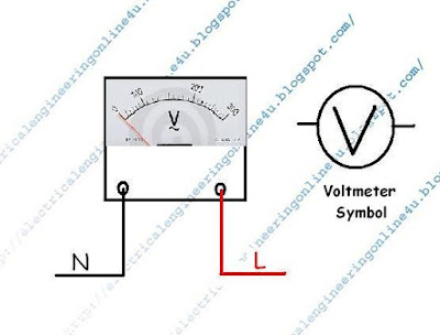
This is very simple to wire the volt meter, just like the we wire a lame holder, the voltmeter have two terminal just like a lame holder, to wire connect the electric supply wire to the both terminals as shown in below diagram.

voltmeter    wiring diagram


In above voltmeter wiring diagram i shown the a voltmeter with electric supply and as i wire the voltmeter same you can wire and do it same just like i shown in above diagram, how ever soon i will upload practical example which will help you very much. In above voltmeter wiring diagram i shown the voltmeter symbol which can help you in incoming articles.
Hope you learn this circuit, share your ideas with us using the below comments section.

Single Phase Motor Wiring With Contactor Diagram

As you know that we use in every place AC motor for different types of work. There are main two types of AC motors which are single phase and 3 phase. The single phase motor are those motor which is working one phase and neutral (ground) supply for doing his duty and a 3 phase motor required 3 phase power source. However we use mostly in our homes and for small work the one phase motor, in this post you will learn about the single phase motor wiring with contactor / motor starter.

As you know that we use cont actors for 3 phase motor for controlling, and we also know the advantages of contectors, so what bad thing if we instill a contactor for single phase motor. Note that we did not use contactor for one phase motor mostly because this connection can be done by a single or double pole breaker.

But There are many benefits of contactor,
E.g example you can easily switch on motor by pressing a small push button switch, you can easily switch off by easily pushing off button or normal close button.

If the incoming voltage low some time, the magnetic contactor will not set and your motor will be safe form burning in low voltage case.

This is good for those countries where the load shedding problem are living, i use in my home a cont actor for my one phase water pump motor because i am living in Pakistan and Pakistan are numbering in those countries where the load shedding are living.

So my water pump motor is instill so far away form my living room. Now i am telling my story, one day i switch on by one phase water pump motor and after some time the power went. I forgot to switch off the motor breaker and i go to market.


In that time there is no one in my home and after some time after my let off home the electric power come back and motor started automatically due the switch on circuit breaker because i forgot to switch it of f. So When i come back to home and i open my home main door by using the key. I find that my motor was burn due to continuously working or due to low voltage coming. I dont know what happened.

Also Read Below:
How to wire One phase motor with circuit breaker?
How to wire contactor for 3 phase motor?


After rewinding the electric motor, i think about the solution of this problem and safe form this accident again and i find out the motor cont actor is a best for this work.
Now i instill a magnetic contactor with My single phase motor wiring connection for switch off / on and there is no need switch off the motor after load shedding or power went.

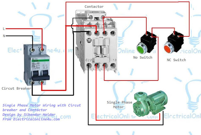
Single Phase Motor Wiring With Contactor Diagram

I chose diagram to tech you online and i always try to write and design by post simple to understand. I also published 3 phase motor wiring diagram which wired wi th contactor. This wiring connection is also easy as 3 phase motor wiring.
You need to wire you normally close and normally open switch with cont actor as i wired in my last contactor diagram. But there is no change between my last diagram that i did not instill the overload relay but you can use reset able overload for protecting your motor. My below single phase motor wiring with contactor diagram is too simple that there is no need to explain it words.
single phase motor wiring diagram

The above diagram is a complete method of single phase motor wiring with circuit breaker and contactor. In the above one phase motor wiring i first connect a 2 pole circuit breaker and after that i connect the supply to motor starter and then i do cont actor coil wiring with Normally Close push button switch and Normally Open push button switch and in last i do connection between capacitor start motor and contactor.
I think know you will be able do the single phase motor wiring with contactor after this diagram.

Hyperikon Ballast Compatible LED Tubes Review

As I mentioned in a previous post I've been working on switching a lot of my lights to LEDs. For standard screw in bulbs it's been very simple. If you have any fluorescent tubes, switching to LEDs was a bit difficult until now. I found these Ballast Compatible LED tubes from Hyperikon that make replacing your fluorescent tubes with LEDs easy.
Read more »

Monday, April 10, 2017

Organizing Cable Clutter

Some helpful tips on how to organize cables around your computer desk, entertainment system and other parts of your home.

Sadly, that's an actual picture of what's lurking under my desk. What's even sadder is that's just one small portion of the mess and it repeats itself in other parts of my home. (I won't mention the peanut I had to crop out so you don't think I'm a complete slob!)

I need a lot of different peripherals and even though I have good WiFi equipment as more people in the area use WiFi it's difficult to maintain speeds good enough to stream full HD video to other computers and TVs. I've bought new access points, built antenna boosters and still have to scan and switch channels fr om time to time. Wired ain't tired! (fake TM)

It's one of the big reasons I'm trying to plan a structured home wiring project. It would get a lot of the cables I have by my computer, and other areas, moved to a central location.

Probably the worst part of the photo is all the dust and pet hair. It's dark down there so I normally can't even tell. I try and vacuum but it's just so hard with that mess. There is definitely no 5-second rule if I drop a snack while at the computer! Partly because it just disappears into the void.

When I have to replace a cord, upgrade a device or try to plug something new in it takes me more time than it should. Over the years I've tried improving my cable management by using different things I had laying around but now it's time to do things right and this is how I'm going about it.
Read more »

What is Electricity Complete Explanation Step By Step

As we know that Electricity is very important thing in every one life, but more of us dont know about that what is electricity in real. Thats way i am writing this post and i written above that many people dont know about electricity what is in real, and you know that i was also one of them, i also did not know completely, but recently a friend + my teacher gave me a book to study this and i find out this question and topic on first page and i start reading and you know i find out this is too interesting and i got some great knowledge about electricity which i am sharing with you in this post. I did not say that this is complete information about Electricity because no one know about it completely that from where the electricity history was started and also no one can learn the all branches of electricity because electricity knowledge is like a sea which have no end.

Electricity

What is Electricity? - A Complete Guide And Basic of Electricity

This question "what is electricity" comes in many people minds and many people relay dont know about this. When we lighting about the properties and advantages of electricity, we find out there is no end and this thing make us to find out the correct answer of this question.
In simple words electricity is power which we can not see and dont have a body and weight but we can fell only if we tech mistakenly electri c wire, we fell a big shock.
If we said that electricity goes inside into electric bulb and make filament red and start energizing but this is bad example for this. However we can said that the power of electricity make energize the light bulb filament.
But we use many examples about electricity actions, For example we get water for example, we can flow the water form one place another place and we can also do this with electricity. As Water have a big power, electricity have also a big power, as we use the pipes for flowing water form one place to other, just like this we use the conductor or copper wires for electric current flow.
But this is also not a good example and its not too related with electricity because the water have there weight and body but Electricity have not a body and wight. And if we touch the electricity, we fell a strong shock which prove that selectivity have internal a great power and that power constrain the electric device to do w ork.

Also Read :

Ohm Law Complete Guide
What are Conductors and Insulators?

Electron Theory :

Every thing have there mass and takes up space is called the matter. There are 3 types of matter Solid, Liquid and Gas. By the help of advance query we find out the every thing in universe is made form matter and matter is made from more smallest particles which we called Molecules. These molecules are also make form more smallest particles which we called atoms.
When Two or more atoms together make a molecule. Note that those substances which molecules are made form same atoms are called Elements and which substances which molecules made form different atoms are called compounds.

Structure of An Atom :

In the world every thing is made form from atoms, Basically atom are comprise&nb sp;three types particle which we called Electron, Proton and Neutron.
Every atom have a center which called nucleus which comprise with neutron proton and electron. Electron are surrounding from nucleus very quickly in orbits.
Electron have negative charge (-) and proton have positive charge(+).

structure of atom animation

The Flow of Electric current :

In the Atom outer shell  electron have a week gravity with nucleus  and can be easy separate free electrons from the atom. As you know that atom is also a smallest particle which have a high number of electrons, in cubic centimeter Copper have almost 10^24 free electrons. If we take example of the copper wire one end as negative and other as positive, then electron start flowing form the negative to the positive.
E.g example we connect a copper wire to energy or provide pressure due this energy the free electron start pushing 2nd atom free electron and the 2nd will start pushing the 3rd atom free electron. And this process is start until the power supply not ended.
In short the process of flowing free electron is called electricity.


Electron Flow Direction

In old time the concept of electron flow was that a substance / thing are moving in electric wire from which we attain temperature and light. This theory was used that the current flow direction is from positive to negative. This theory was called conventional current flow.
But now according the advance atomic theory the flow of electron is negative to po sitive. Its means the regarding the advance electron theory the direction of flow of electron is from negative to positive.

electron flow animation

Electron Flow

The electron flow is required the pressure (potential difference) voltage in a conductor, These provide pressure from 2 ways with generator and battery. But when this pressure is stop, the flow of electron is also stop. Its means that continue electric current flow required 2 main things electric wire and continue voltage.
If we dont have one them then we can not make the flow of electron or electric current.


Some main Names we Face in Electrical Technology


There are some name and things which is relate to question "what is electricity" and electrical technology

Current:

The flow of free electron is called current, current id denote by "I" and its unit is Ampere.

Voltage

The pressure required to flow the electric current, voltage is denote by "V" and its unit is Volt.

Resistance

The property of a substance which opposes the flow of current or electricity through it is called Resistance or resistance is the ability of circuit to oppose current. resistance is denote by "Ω" and its unit is ohm.


History of Electricity - Names related with Electricity History


(1) :                  William Gilbert (English Physician) is known as the owner of Static Electricity who described in his  book "that by rubbing different material with Amber make Amber different form load stones. This prove that from rubbing the Amber with fabric (cloth) then amber attract small things while the load stones only attracting metal. Gilbert invention that other things like Glass,Resin are also working like Amber and use a Latin word "Elektron" for Amber and chose Electrica for other things with same working properties.

William Gilbert


(2) :  Word "Electricity" was first used by English Physician the Sir Thomas Browne (1605 to 1682).
Sir Thomas browne


(3): After that a English Scientist Stephen Gray (1696-1736) discover that some things dont allow the flow of electricity and some are allow flow of electricity.
Stephen Gray


(4) :  Benjamin Franklin was a politicisation and scientist Who conceive of  Positive and negative.

Bengamin Franklin

(5) : Charles Coulomb (1736-1806) was french physician who developed the Coulombs law "which is about the electrostatic force of attraction and repulsion in 1785. Thats way the SI unit of charge is called Coulomb after that.

The History of Electricity is too lengthy and this post is about " what is electricity " not about history however i will write about in another post when i got some free time because is this is not too important and i required to collect the  all information of he story of electricity. However this post is about what is electricity and i try my best to tech you about electricity. I dont like more lengthy post because a high number of words and lengthy post is a boring post and i dont want to bore you....

Sunday, April 9, 2017

How to Wire 3 Pin Socket outlet

Today in this post you will learn about 3 pin socket wiring which very useful wiring connection in home wiring. In this post i am sharing with you three pin socket or electrical power outlet wiring diagram.


Why three pin socket wiring connection is important

Because this is a power socket and we can use it for high load.This outlet have earthing point we can wire the earth wire with this socket.

How to Wire 3 pin socket

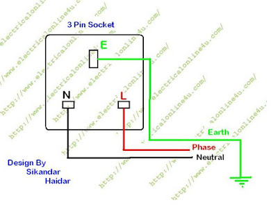
In three pin socket we have 3 connecting point where we connect the supply wires or electric wires. These are E,N,L connection. In these E for Earth wire, N for Neutral wire, and L for Phase wire.
So to wire the power socket first of all switch off your incoming supply by using the main circuit breaker and the start wiring.

Also read.
How to wire a two pole circuit breaker

After switching off the breaker connect the neutral wire to the N point, Phase wire to P or L point and Earth wire to the E point as shown in below diagram.

3 pin socket wiring diagram
3 pin socket


I hope after diagram, you will completely learn the 3 pin socket wiring, now if you have any question then do ask me.

How to Wire Batteries in Parallel

In our daily life we use batteries, and mostly we use it in 2 types of connection in which one is " Wiring batteries in parallel and 2nd in series ". In this post you will learn that how to wire batteries in parallel connection with explanation diagram.

How to Wire 2 Batteries in Parallel


To wire 2 or more then 2 batteries in Parallel connection, e.g example if you have two batteries and you want to wire it with each other in parallel. So if your first batter is 12 volts and 200Ah and your 2nd batter same just like first. So you have two batteries of 12 volts and 200Ah. So When you connect both batteries in parallel then the volts (V) will be same 12 volts but your  Ah (ampere hour) will be plus 400Ah.
Now lets come to the wiring connection, for this type of batteries wiring, connect an electric wire between B1 positive B2 posi tive terminals and then connection an electric wire between B1 negative terminal B2 negative terminal.
Now you make a batter which is 12 volts and 400Ah. After that get supply form the batteries as shown in below diagram.

wiring batteries in parallel
In above batteries wiring diagram i shown that how to wire your batteries in parallel and how you can get supply from this. Now if you have any question regarding this post or batteries in parallel then write your word in below comments section.

Saturday, April 8, 2017

How to Wire a 2 Way Switch

In our daily life we use two way switches, but most people dont know about the 2 way switch wiring, for that i am gonna to write about this switch wiring with complete diagram. Most of people think that in electric wiring we use 2 way switch only for stair circuit, but they are wrong , because the uses of 2 way switch in electrical technology so many. We use in Washing machine, We use it for two electric supply etc.

How to Wire a Two Way Switch

In 2 way switch we have three terminal, in which one is common and 2 are for different connection and different supply, it is depends on your use and work, however i am try to explain it uses using below diagram.
In below diagram i shown switch symbols for explanation and function.
two way switch symbol
In above example i shown in one symbol that you can gave supply to common wire and can get supply from 2 terminals and in second switch symbol i shown that you can enter two supply and can get a supply form common terminal which you want. You can use it regarding your work in many places.


Message

I hope you understood that how to wire a two way switch, however for better understanding soon i will write about the complete examples. However you can ask your question in below comments section.

How to Wire Electrical Outlets Plug Sockets

The electrical outlet wiring / plug socket connection learning is very important for electrical students and just for that this post is about how to wire electrical outlets. For today post i make a electrical outlets wiring diagram in which i shown that how to do wiring of outlets / plug sockets. In this post post you will learn that how to wire electrical outlets / 2 pin sockets with AC supply, however i will post soon about UPS wiring and and instillation of electric home wiring.

Requirements :
Electrical outlet : 4 outlets / two pin sockets
AC supply : 110 volts OR 220 volts AC incoming supply


For socket & outlets wiring," first of all switch off your main circuit breaker and then connect the neutral and phase wires to plug sockets shown in below image / diagram. Then Switch On your circuit Breaker


wiring of electrical outlet

Also Read Below :
How to wire one pole circuit Breaker
How to wire 3 pole circuit breaker for 3 phase supply


In above diagram i shown the complete wiring method of electrical outlets or plug sockets, However i want share with you a video about instilling an electrical outlet which help you more. Watch the below video tutorial.


Now i hope you completely understood and now you can wire and instill el ectrical outlets in your home. Keep visiting.

Friday, April 7, 2017

Submersible Pump Control Box Wiring Diagram For 3 Wire Single Phase

Today i am hear to write about submersible pump control box wiring diagram , in this post you will complete understood about 3 wire submersible pump wiring diagram which is an single phase submersible pump motor. Why we called a single phase submersible motor a 3 wire submersible, that we also know that we have two wire in single phase power supply.
As you know that we have two types of winding in a single phase motor and these coils have also two starting and finishing ends, So we connect one one end of each coils and make a common point which know also with name of common point. And the other ends called starting and running terminals or connection. So we have 3 wire terminals or wire which out form the motor , thats why we called this 3 wire motor.
In the post you will completely learn about single phase submersible pump control box wiring diagram, and this diagram not to hard to understand like t here own diagram which is mostly available in control box back side.

Single phase submersible pump control box wiring diagram - 3 wire submersible pump wiring diagram


In submersible pump control box we use a capacitor, a resit able thermal overload and DPST switch (double pole single throw). The wiring connection of submersible pump control box is very simple. Here is the complete guide step by step.


  • First of all switch of the main circuit breaker in your distribution board, this for that reason that you can work safely and protect himself form electric accidents.
  • Then connect the supply to input wire connectors. 
Now if the box is not wire then flow the steps and if the box is wired then last steps is for you.

  • After that get connection from wire connectors and then connect your neutral and Line wire (hot wire / phase) to the double pole single throw switch as i shown in the below diagram.
  • Then get hot wire connection form DPST switch and connect to the reset able thermal overload protector. And form overload protector connect this (black wire) to one of the output wire connector.
  • Now get your neutral wire (blue) form the switch and connect to capacitor, and form same terminal of capacitor connect it to one of the output connector.
  • Then connect a wire form other free side of capacitor terminal and connect to the one of the out wire connectors which i shown with red or brown color in diagram.
  • In 1 number connector connect your ground or earth wire as i shown in diagram with green color.


Now you have 4 out put wire connector, in which 1 number for earth connection, 2 number for starting terminals because this wire comes form capacitor, 3 number for run ning wire for motor and 4 number for common.
So you need to connect the running, starting and common wire of submersible pump to control box, so mostly in submersible pump 3 wires the Black color wire is common, Blue is Running and Brown or red for starting, But these color can be change or may be in your submersible pump different color wire are used. 

First if you know about the starting, running and common wire then connect it box connector as i shown in the below single phase 3 wire submersible pump box wiring diagram.

submersible pump control box wiring diagram
single phase submersible pump starter wiring diagram


Now if you did not know about the star, run and common wire in your pump motor then follow the below compressor terminals identifying tutorial and same follow the steps to find out identify submersible pump wires start,run and common. (Note that identify compressor terminals and submersible wire method is same)

Also read
How to identify start , run and common in single phase motor or compressor?
How to control a single phase motor using circuit breaker?
How to wire resetable overload?
How to control and wire a single phase motor with contactor?


In the above wiring diagram i shown the complete method of submer sible pump control box wiring and installation diagram. Now if you have any question regarding single phase submersible pump starter wiring diagram then you can use below comment section.


Ceiling Fan 3 Wire Capacitor Wiring Diagram

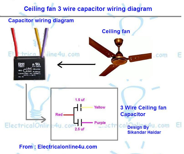
As you know we use single phase types motor in ceiling fan and a ceiling fan required capacitor to run. In ceiling an we use capacitor, in which one type capacitor have 3 wire. In this post i am gonna to explain the ceiling fan 3 wire capacitor wiring diagram. This capacitor have 3 wires in which one is common for both and other two for different value capacitance. My means that there are two capacitor instill in this capacitor and both value is different from one another.


Ceiling Fan 3 Wire Capacitor Wiring Diagram

The 3 wire fan capacitor diagram mostly available on capacitor but most people did not understood. And he always try to buy a 2 wire fan capacitor. But the 3 wire capacitor is better than 2 wire because we can use if for two different requirements.
In this capacitor one wire is common and between common wire and 2nd wire the capacitor is different then between common and 3rd wire.
One thing more in some ceiling fans we use this type of capacitor for regulating speeds. I.e example that form example when the fan motor start on 1.5 uf the motor will be on low speed and when the capacitor on 2.5 then the motor will be on med speed and when ceiling fan motor run on both capacitor in same time (1.5 + 2.5 = 4 uf) then the motor on high speed.  And as i told in my above words that we can use it for a fan motor which only required the 1.5 micro farad capacitor.
However ceiling fan 3 wire capacitor we use in fan for mostly for speeds. In fan we use speed regulator switch form which we can regulate the speed using capacitor.
We have 3 wire is ceiling fan capacitor in which red is common and other two are for different capacitors values.


Also read
How to connect capacitor to fan ( ceiling fan capacitor wiring diagram)?
What is role of capacitor in fan ?

First i am gonna to explain the 3 wire capacitor diagram and you can easily learn form below three wire capacitor diagram.
ceiling fan 3 wire capacitor wiring diagram

As i shown in the above ceiling an 3 wire capacitor diagram that red is common wire and yellow for 1.5 microfarad and Purple for 2.5 farad. However IN SHA ALLAH in further post i will explain the fan 5 wire capacitor, regulating speed switch diagram and replacement of fan capacitor in fan motor.
Now i hope you understood about the ceiling fan 3 wire capacitor wiring diagram. Now if you have any question or suggestion then post on comments box bel ow.


Thursday, April 6, 2017

Voltmeter Selector Switch Wiring Diagram For Three Phase

Last time we talk about selector switch and i explain selector switch wiring connection and instillation for ammeter and with current transformers. Now in this post i am writing about voltmeter selector switch wiring diagram for three phase. As you know that if we instill the three voltage meter for 3 phase then its will be a big lost of money.
But we also need to measure and test the all phases voltage. So if we instill a voltmeter selector switch then we can measure the voltage of all phase with one voltmeter. So we dont need to instill three voltmeter for 3 phase and we can save a big money by using the selector switch.

Also read
How to instill and wire ammeter selector switch for 3 phase?

voltmeter selector switch wiring

Voltmeter Selector Switch Wiring Diagram For 3 Phase


The wiring connection and voltmeter selector switch wiring diagram is too simple and the connection is same as we do for ammeter selector switch, same we connect the L1 L2 and L3 supply connection to R,S,T.  And get connection for A1 and A2 to voltmeter as shown in above voltmeter selector switch wiring diagram.


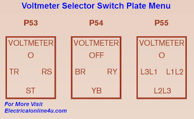
The above diagram, i get form an online book which i share with you on this post. The voltage meter selector Escutcheon Plate are available in three menu types, and you can test and measure voltage between two phases by using knob. These plate menu are available in (0, TR, RS, ST) , (Off, BR, RY, RB) and (0, L1L3, L1L2, L2L3). You can see in below.

Escutcheon menu plate of selector switch

I hope you enjoy this post and learn the voltmeter selector switch wiring and instillation from this post. Share this post with your friends and like us on social media.

What is Magnetic Contactor and How Its works

We know that for power wiring / 3 phase motor wiring we use mostly the magnetic contactor or motor starter. In this post we will study the magnetic contactor importance, working / function and its uses in electrical technology. I also share post about M contactor wiring diagram but this post specially for function and working of 3 phase contactor or motor starter.

What is Magnetic Contactor?

We can also said that a contactor is type of electrical relay which we use for power electric motor to start or stop. Contac tor make easy to controlled 3 phase induction motors. We know that 3 phase motor required three phase supply to run, 3 phase supply is two dangerous which we can not handle with a circuit breakers for induction motor. Contactor make easy to handle the 3 phase motor controlling. The parts of the magnetic contactor are coil, iron core, 3 contacts points and NC, NO points.

magnetic contactor
Contactors

How a Magnetic contacor Works

The function of a contactor or motor starter is simple, when the AC supply goes to the contactor coil, the coil make a strong magnetic field and field pulls the iron core to the coil and make a electrical contacts.

What are NC, NO in Contactor
The NC means the Normally close electric circuit or we can said it is a normally close contacts and NO meas normally open contacts. In normal state when contactor coil does not energize the NC point is normal close state and when the coil energized these these NC contacts create a NO contacts between one another, after coil deenergized NC contacts make a close circuit.
Same the NO contacts change on coil energizing to the NC contacts.

Also read

Advantages of Contactor

There are many advantages of 3 phase contactor but some are very important which are below.
You can controlled power motors easily by pushing a small button.
You can ON/OFF electrical 3 phase motor in small time.
You can safe him self for electric shock in 3 phase motor starting.

Wednesday, April 5, 2017

How To Wire a Switched 3 Pin Socket

In my last post i share a 3 pin socket wiring diagram, in this post you will learn that how to wire a switched 3 pin socket or how to control a 3 pin socket from a circuit breaker. This wiring diagram is impotent because by using this wiring connection a person can easily switch off the 3 pin socket or can easily switch on by using the circuit breaker


How to wire 3 pin socket with circuit breaker

To wire a switched three pin socket, first of all connect the earth wire to E connection of socket and then connect the Neutral wire to N point of socket and connect the Phase wire to circuit breaker and then connect a wire between circuit breaker output terminal and socket L or P terminal as show in below diagram.

3 pin socket wiring with circuit breaker
three pin socket

I hope know you will be able to wire a switched three pin socket using socket and circuit breaker. Share our blog with friends if you learn some thing. Thank you.

How To Wire Ammeter With Current Transformer CT Coil

In my last post i guide you about the ammeter wiring which is only for low load and in this article you will learn that how to wire ammeter for high load or High ampere testing. In this post i am sharing with you a diagram in which i wired an ammeter with current transformer which is well know with his short name CT Coil.
By using the ammeter and CT coil we can measure high load ampere, Note that we use this wiring method for power wiring and by using this ammeter wiring we can test, measure high load circuit or ampere.


To wire the ammeter with current transformer, follow the below method, in the below diagram i shown that how wire the ammeter with CT coil. In the CT coil have to terminals which are negative and positive - and  +. Same ammeter have two terminals - and +. To wire ampere meter connect the CT coil positive to ammeter positive terminal and CT negative terminal to ammeter neg ative terminals by using the electric cable as shown in below figure.

ammeter
ammeter wiring diagram

For measure the ampere using the ammeter and current transformer pass the electric supply wire between the CT hole as shown in above diagram. Note that pass only one wire between the CT Coil.

Message :
I hope now you will be able to do the ammeter wiring after visiting this site, for more update and learning stay tune with us.

Tuesday, April 4, 2017

How to Wire A Frequency Meter Hz Hertz

Today i feel that i am the number one who write about ac frequency meter wiring for measuring hertz. In this post you will learn about that how to wire frequency meter or how to instill a panel Hz meter. This meter we mostly wire and instill in AC Power Generator, we can also called it a rpm meter.

What is frequency meter?

We use this meter for measuring frequency, in mostly 110 volts usage places the frequency is 60 Hz and in 220 volts is 50 Hz. However lets know that how to wire it.

Also read below:
How to wire volt meter?
how to wire a amp meter with CT coil?

How to wire a frequency hertz meter?


The wiring of H z meter is too simple just like wiring an voltage meter or outlet. For wiring connect the neutral and phase (Line) to the meter connection terminals. I shown neutral with N and phase with L in below diagram.

frequency meter Hz meter wiring


I hope you completely understood, in the above diagram i shown that how to wire an Analog Hz meter, however soon i will post about the digital meter wiring diagram and instillation.

3 Phase Wiring Installation In Multi Story Building

In house wiring, we instill two types of wiring in which one 3 phase wiring installation for house and other one single phase installation. In this post you will learn how to instill three phase electrical wiring using a simple diagram in which i shown how to instill three phase 4 wire system in a multi story building. One thing more that i shown 3 distribution boards in which every story have there own electrical main distribution board.

3 Phase Wiring installation In Multi Story Building / House


The three phase 4 wire system installation in home is very simple but to understand you must study each part of this class and devices which i use in the below diagram. I start form this from step one.

Utility Pole 3 Phase 4 Wire System

In the diagram is start form the u tility pole and i get service line supply form utility pole to 3 phase kWh energy meter. This utility pole connect to step down transformer (supply from sub station). My means that the pole supply comes form the substation or step down transformer.

3 Phase kWh Energy meter

I also shown the wiring diagram for there phase 4 wire system kWh (kilowatt-hours) meter, I also published a post about the wiring and installation of three phase four wire system kWh energy meter. So kindly read the below article if you did not understand the method of 3 phase kWh energy meter connection.

Also read
How to wire and instill the 3 phase kWh energy meter?
How to wire Single phase kWh meter?

4 Pole MCCB Breaker

After the connection of energy meter, i connect the 3 Phase 4 wire power supply to the MCCB (module case circuit brea ker). However if you can do this connection then read the below post.
Also read
How to wire 3 Pole or 4 Pole MCCB Breakers?

Now come to the connection for distribution board for one story. The method of installation 3 phase wiring is simple, you divide your load in three parts and each part have there own Line (phase). My means that divide your load in 3 parts and provide one one phase to each part.
Now here i have multi story building in which each story have there own single phase distribution board.
So we will provide one one phase or line to each story. And our neutral will be common but this will be common in circuit breaker output point and each story have there own neutral wire. So provide my Line 1 or phase 1 to the first distribution board and you can see in diagram. So come to Distribution board.

Distribution Board Wiring Connection

In the db board, i use the follo wing electrical devices.

Double Pole MCB Circuit Breaker 63 Amps

I get phase and neutral wire form the main circuit breaker( 4 pole MCCB) and connect to double pole MCB (miniature circuit breaker). Note that double pole MCB will be consider a main circuit breaker for single phase distribution board for below diagram.

Also read below
How to wire double pole MCB breaker?
How to wire and instill single , double , three and four pole MCB (miniature circuit breakers)?


RCD Brekaer.
I also instill and wire double pole RCD (residual current device) in each distribution board. If you did not understand the wiring and instillation of RCD then read the following post.

Distribution Electrical board Wiring for Single phase
How to wire and Instill the double pole RCD breaker?
How to wire a 4 pole RCD circuit breaker?

Earthing or Ground connection

I also done the earthing connection in 3 phase wiring installation diagram in multi story house. I shown this connection by using a earth symbol and green wire. In the below diagram the earth symbol consider as earth electrode.

Also read
How earthing system works for protection?

AC Voltmeter Wiring connection for single phase

I also do the voltmeter wiring connection is each distribution board and you can see it in diagram. However here is some post which help you more then this. (Note that the VM denote the ACV voltmeter in below diagram.

Also read
How to wire a voltmeter for single phase?
How to wire a voltmeters for Three phase?
How to wire voltmeter selector switch for 3 phase with volt meter?
How to instill the volt meter selector switch for 3 phase 4 wire system?
How to wire light indicator for 3 phase 4 wire system?

Ampere meter / Ammeter connection with CT (current transformer)

I also shown the ammeter connection with current transformer in 3 phase installation diagram for multi story house. The connection of CT is simple with ammeter but this will be better for you if you read the following articles.

How to wire a ammeter for AC and DC?
How to wire ammeter with current transformer?
How to do digital ampere meter connection with CT Coil?


Complete Explanation of Three - 3 phase wiring installation in a multi story building


The installation of three phase 4 wire system in multi story building is simple if you want to use single phase supply for each story. Note that by doing this type of connection you must wire 4 distribution board where one for main MCCB circuit b reaker and other for each story. And you can also do these connection in a single main DB but you must use a big size  distribution board box where you can easily instill all circuit breakers. But if use there own distribution board in every story then this will be better option.


So lets do it step by step.
In the 3 phase wiring diagram i shown a utility pole from where i get service line connection for 3 phase kWh meter (energy meter). Now i connect the supply wire Red, Yellow , Blue and Black to the energy meter input connection terminals and get supply form energy meter out going connection to load.
One thing more that that we use color code of red yellow and blue when we are doing the three phase wiring but when its come to the 3 phase four wire system, we use the black for neutral. And when we are gonna to doing connection of single phase ( current between phase and neutral) then we use red for phase (hot wire) and black for neutral.

< br />After the connections of three phase kWh meter we provide the 3 phase 4 wire supply to 4 pole MCCB circuit breaker which on th- 100 amp. Now the next step is outgoing supply form the 4 pole MC CB circuit breaker. The N neutral wire will be common for each story or load and you see it in the below diagram, that i connect the neutral black color wire from the breaker and wire it with a connection point connector.

So the neutral will be common for each story or distribution board and one one phase will be distribute to the each story. So i connect the neutral wire to a neutral connection point or connector from where we can get connection of neutral for load.
I connect a neutral wire to this neutral connection point and connect to the story 3 distribution board double pole MCB breaker. And then i get Phase wire form the MCCB and connect to this MCB breaker. Then MCB supply goes to the double pole RCD and you can see it in below diagram. Note t hese two breaker are 63 amps.

3 phase wiring installation diagram


Now form the RCD breaker the neutral wire goes to neutral connection point as i shown in above 3 phase wiring diagram and the phase (hot wire) red color is goes to all single pole MCB breakers which i shown in above diagram.
In the above3 phase wiring diagram the 2 single pole breaker are 16 amp , 2 are 10 amps and other sex are 6 ampere breaker. Note that this just in example and you must instill or wire breaker regarding your total load. Note that use high quality wire for you r wiring system. And always chose or use the wire regarding load (amps).

I also wire the voltmeter in above three / 3 phase wiring third story building wiring, for which i get hot wire connection form input points of single pole MCB breakers and neutral from neutral connection connector point. And same i wire the light indicator.
In the above diagram i shown the ammeter connection with current transformer (CT coil) and also provide the complete method of wiring and installation of ammeter with current transformer in above links. However use always the current transformer regarding the ammeter requirements. If the ammeter is 60/5 then use a current transformer with same value 60/5.
You can also use AC series type of ammeter but the CT type ammeter is better then ammeter which we use between supply in series connection.

As i shown in above 3 phase wiring diagram that i do the earthing connection, and provide the earth wire to each point. I sho wn in bottom of diagram earth symbol with name of earth electrode and from here i provide the ground connection to all story loads / rooms etc. And in each story i use the earth connection point, from where a person can provide the earth wire to any load / electrical machine, outlets etc.

In the above 3 phase wiring diagram 1,2,3,4..... in circle means that these wire goes to load 1 , load 2 and load 3. Its mean that if the 1 hot wire (phase - red) wire goes to the room A then the neutral 1 (black wire) is also for the room A and the earth connection 1 number wire is also for the same point (load- room A).

Follow the same method for story 1 and story 2, but provide the L2 (phase 2 - Hot wire 2 ) to the story 2 and Line 3 to story 1 which is bottom of 3 phase wiring diagram. However lets get another review on diagram step by step.

3 Phase Wiring Step By Step Guide Multi Story Building


  • First of all provide the serves line wire to the 3 phase kWh meter from utility pole.
  • Then provide the 3 phase 4 wire supply to 4 pole MC CB Circuit breaker.
  • Then connect the neutral point form MC CB to neutral connection point.
  • Then get connection from the main neutral point and connect to story 3 or other story double pole MCB circuit breaker.
  • The connect the L1 to the story three double pole MCB between the CT (current transformer) and form MCB connect neutral and phase to the RCD circuit breaker. (Note some people know RCD with name of ELCB  (earth leakage circuit breaker).
  • Then from RCD connect the neutral wire to neutral connection point and phase to circuit single pole breakers.
  • Then provide the supply to the voltmeter and indicator light.
  • Then Do connection between CT coil and ammeter.
  • Then provide the earth connection (green wire) to story three earthing connection point.
  • Then pr ovide the supply to each loads form circuit breaker , neutral connection point and earth / ground connection connectors.
Thats all , same follow this method for each story. but provide there own different phase wire and neutral wire.

Message:

This in example of 3 phase wiring installation in multi story building, and i use different ampere circuit breaker, just for your understanding. However always use breaker regarding your load. Now i hope you understood the 3 phase wiring in multi story house or building, now if want gave us suggestion or any question then use the below comments section. 


Monday, April 3, 2017

Energy Efficient Window Treatments

Windows provide light and views to the outdoors but the heat loss through even a double pane window can still be up to 10 times the heat loss through an insulated wall. Window treatments can boost the R-value of windows as well as add to the decor of a room. Im working on a plan to redecorate some rooms of my home and have come up with the following window treatments plan to help keep the cold out during the winter.

Window Treatment Requirements

There were a few key features I was interested when I was planning out my window treatments. 

Energy Efficient - First and foremost I wanted my window treatments to help make the room more comfortable.

Provide Privacy and Light - Im currently using opaqu e blinds which provide me with privacy or light but not both at the same time.

Light Control - If Id like to darken the room I have that option.

Attractive - The window treatments should add to the aesthetics of the room, not detract from it.

Window Treatment Layers

Just like dressing in layers to keep warm, dressing the windows in layers also helps increase the energy efficiency, versatility and visual appeal of the windows. The layers will consist of bubble wrap stuck on the glass (for some windows), a double cell honeycomb shade and a set of thermal lined drapery panels capped with a closed top window cornice.

This wi ll create additional 4-5 additional air pockets, in addition to the air pocket within the double pane glass, which increases the insulative capacity. The first air pocket is within the bubble wrap, second is between the window and cellular shade, 2 air pockets within the cellular shade and finally the air pocket between the shade and drapes when the drapes are closed.

Bubble Wrap

The bubble wrap increases the insulation of the window. It will obstruct the view but will still allow light to pass through. It will be applied to the windows once the weather drops and removed when it starts to warm up and only used on windows that I dont care too much about the view.

The bubble wrap needs to be cut to fit the glass of the window. Mix up a solution of water with a drop of liquid soap and spray it generously over the glass and press the bubble wrap on the window just like when applying window film. It will keep the bubble wrap in place and make it easy to remove in the Spring. If stored carefully the bubble wrap should last a number of years.

Double Cell Honeycomb Shades

The next layer will be double cellular shades which help insulate the window by providing 2 air pockets within the shade. The shades are light filtering so they allow some light to enter the room even when the shades are covering the windows. Many come with a top-down/bottom-up feature which allows the shade to be lowered from the top to allow for more light and a bit of view while still providing privacy. The one drawback compared to blinds is th at you cant have good air flow and some light and privacy.

The most energy efficient cellular shades Ive seen are these Comfortex Energy Efficient 3/8" Double Cell Shades. In addition to providing the increased r-value that double cell shades do, their ComforTrack side track increases the r-value by about 17% (r-value 3.3 vs 2.8) by further restricting airflow at each side of the shade where it meets the window jamb. The shades are also available as blackout shades if youre interested in installing them in a home theater or bedroom. Personally I like the idea of light filtering shades with room darkening or blackout curtains instead of blackout shades.

The Comfortex Energy Efficient Cellul ar Shades arent cheap. Theyre about twice the price of the Blinds.com 3/8" Double Cell Shades which dont come with a track but do provide better insulation compared to my current blinds. 

Thermal Lined Curtains

To further increase the energy efficiency as well as provide additional light control a pair of thermal lined curtains will go over the window and shades. A couple of years ago I installed 2 different types of thermal/blackout curtains. Some were Eclipse Blackout Curtains and the others were from Best Home Fashion. While theyre both labeled as blackout&nb sp;curtains they didnt block all light from coming in, at least not in the light colors I purchased them. They did dramatically darken the room though and helped the room feel more comfortable during the winter.

Window Cornice

When the heating system is on, air circulates around the room through convective currents. Warm air rises, cold air falls. To minimize the amount of air that passes behind the curtains, and thus reducing heat loss, a closed top window cornice will be installed. You can view my instructions on how to build a window cornice.

Choosing Daylight or Warm Color Bulbs

These days when it comes to energy efficient lighting there are a lot of choices. One of those choices is the color temperature of the light. No longer are we stuck with orange for incandescent, green for fluorescent. Using light bulb color wisely in your home can have positive effects on your and your families lives. Below you'll find my tips for choosing light bulb color.
Read more »

Sunday, April 2, 2017

How to Wire a Plug Socket

The wiring of a plug socket is too simple and easy but a beginner E technologys student did not do it him self until he learned. Some years ago learning too hard and a person can not learn electric wiring with out doing practically job with a electrician or without learning in institute but now you can learn it easily using Internet. Today is the day of new year and this blog is the gift from me for all people.
So this post is about the wiring of a 2 pin plug socket and in this post you will completely learn that how a person wire a plug socket.

Requirements:
AC supply : 110 to 220 volts
Plug Socket : 1 two pin socket


Method of wiring of two pin plug socket :
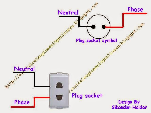
This is too simple, first connect the neutral wire to one of the terminal of plug socket and then connect the phase wire to 2nd terminal of socket as shown the below image / diagram.

wiring of plug socket with symbol diagram

In above example diagram i shown that how can you wire a socket easily, remember first switch off your incoming supply circuit breaker and then start wiring.

Message :
If you learn some thing then share this post with your friends and keep visiting.

How to Connect Batteries in Series

We use mostly use batteries in our life and we connect it two connection, connecting batteries in series is a connection which we use it mostly when we have two 12 volts batteries and we required the 24 volts DC supply.

Also Read Below :
How to wire Batteries in Parallel?

How To Wire 2 Batteries In Series?

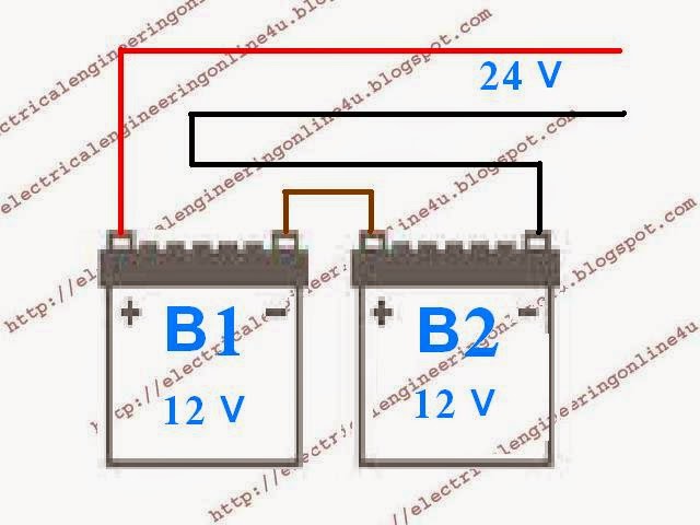
For connecting 2 batteries in series, first of all connect a wire between B1 Negative terminal and B2 positive terminal. Note that use a strong and high gauge of electric cable. Thats all you done it, now you can get 24 volts of supply from B1 positive terminal and B2 negative terminal as shown in below diagram.


connecting batteries in series
Batteries in series

Batteries in Series Connection

In series batteries volts will be plus, e.g if you have two 12 V batteries and if you connect both series with one another then your total volts will be 24 V, and Ah (ampere hour) will be same.
So if you required 24 V DC then you can easily get it from two 12V batteries easily by connecting both in series.

Tom Builds A New Web Design

Tom Builds Stuff get's a face lift. The new design should hopefully make it easier to read plans and view images. The site works better on mobile devices too including tablets and even televisions. Wherever you may be browsing TBS from.
Read more »

Saturday, April 1, 2017

RJ45 Ethernet Cable Wiring Diagram

This article shows how to wire an Ethernet jack rj45 wiring diagram for a home network with color code cable instructions and photos.and the defference between each type of cabling crossover , straight through

Ethernet is a computer network technology standard for LAN (Local area network). It was introduced commercially in 1989 and became IEEE Standard 802.3 in 1983. It has good backward compatibility and it runs at 10Mb, 100Mb or 1Gb per second. It can use a star topology (standard UTP cable) or a bus (old coaxial cable).

What is RJ45 ?

RJ45 connectors also known as 8P8C - (ISO 8877) are a kind of Unshielded Twisted Pair cables (UTP).

RJ45 Ethernet Cable UTP Wiring Diagram

There are two standards that are used for RJ45 connector wiring. They are EIA/TIA 568A and EIA/TIA 568B. They can also be known as T-568A and T-568B. Both standards can be used to make Ethernet UTP network cable. The cable could be a straig ht-through cable or a cross-over cable

WIRING DIAGRAM OF EIA/TIA 568A ETHERNET CABLE


rj45 ethernet patch cable wiring diagram straight trought  568 a

 Color codes of straight trought  standard TIA/EIA 568 A :
  • Pin 1 is White Green 
  • Pin 2 is Green
  • Pin 3 is White orange
  • Pin 4 is Blue
  • Pin 5 is White Blue
  • Pin 6 is Orange
  • Pin 7 is White Brown 
  • Pin 8 is Brown 
Pin Functionalities :
  • Pin 1 is “TX+_D1” or Transmit Data+
  • Pin 2 is “TX-_D1” or Transmit Data-
  • Pin 3 is “RX+_D2” or Receive Data+
  • Pin 4 is “BI+_D3” or Bi-directional+
  • Pin 5 is “BI-_D3” or Bi-directional-
  • Pin 6 is “RX-_D2” or Receive Data-
  • Pin 7 is “BI+_D4” or Bi-directional+
  • Pin 8 is “BI-_D4” or Bi-directional-

WIRING DIAGRAM OF EIA/TIA 568B ETHERNET CABLE 


The pin description and names are the same as that for EIA/TIA 568A Ethernet cable. But the position of the different colored wires varies for both.
For optimal performance, a single cable has to be used for pins 1 and 2, pins 3 and 6, pins 4 and 5 and pins 7 and 8.

rj45 ethernet patch  straight through cable wiring diagram  568 b color code

 Color codes of straight trought  standard TIA/EIA 568 B :
  • Pin 1 is White orange   
  • Pin 2 is Orange  
  • Pin 3 is White Green  
  • Pin 4 is Blue
  • Pin 5 is White Blue
  • Pin 6 is Green
  • Pin 7 is White Brown 
  • Pin 8 is Brown 

WIRING DIAGRAM OF ETHERNET CROSSOVER CABLE 

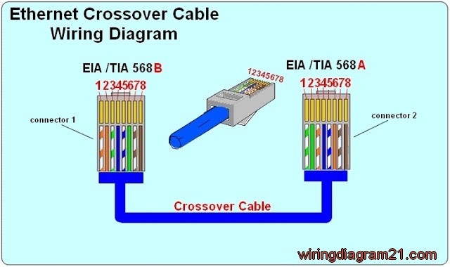
A crossover cable contains a 568A specification at one end and a 568B specification at the other end.

rj45 ethernet crossover cable wiring diagram color code
 Color codes of crossover cable :
       
        & nbsp;    Connector 1                                                                               Connector 2
  • Pin 1 is White orange  ------------------------------------------->  Pin 1 is White Green 
  • Pin 2 is Orange            ------------------------------------------->  Pin 2 is Green
  • Pin 3 is White Green   ------------------------------------------->  Pin 3 is White orange
  • Pin 4 is Blue                --------------------------------------------> Pin 4 is Blue
  • Pin 5 is White Blue     --------------------------------------------> < /b>Pin 5 is White Blue
  • Pin 6 is Green             -------------------------------------------->  Pin 6 is Orange
  • Pin 7 is White Brown ---------------------------------------------> Pin 7 is White Brown 
  • Pin 8 is Brown            -------------------------------------------->  Pin 8 is Brown

How To Crimp  Rj45 cable :


Items needed to wire an Ethernet cable  
  • Crimper
  • RJ 45 Connectors
  • Bulk Cable
  • Cable Tester
  • Wire cutter
Steps for wiring an Ethernet cable

  1. Roll off the cable to the desired length plus a little extra and cut it.
  2. Strip the outer jacket of the cable using a stripper or a knife. You can strip of about 3 cm length. There are 8 wires that are twisted in 4 pairs. Each pair of wire has a wire of a distinct color. There will be another wire that is striped with the matching color of its partner. This wire is known as a tracer.
  3. Check the wires for any cut that is exposing the copper wire inside. If there is any like that, you might need to cut the wire and start again. If copper wire is exposed, it could lead to poor performance or cross talk.
  4. Untwist the pairs of wires and align them in the right order. You should refer to the diagram above to check the proper color orientation for each wiring standard. For a cross over cable one end is EIA/TIA 568B and the other end is EIA/TIA 568A.
  5. Keep the end of the wires flat and trim their ends leaving about 12.5 mm on length. Insert the wires into the RJ-45 plug while holding the connector or clip down. Ensure each wire is pushed deep and examine the connection again to confirm the arrangement.
  6. Hold the wire and place the plug into the crimping tool. You can also double crimp to ensure that the pins are properly set.
  7. All the steps above should be repeated for the other end of the cable.
  8. Now the Ethernet cable should be tested. You can test the connectivity from pin to pin or use a network cable tester. 
Helpful Tips & Hints
  • If the Ethernet cable does not work, check that the pins of both ends are connected. You can cut off the connector and repeat the steps above if not. Ensure that the connector is tightly crimped.
  • The network cable length segment could be as long as 100m or even 150m in some cases. ‘
  • Cat 5e cable is now the standard used instead of the Cat 5 standard. Cat 5e allows for longer distances and allows for far end cros stalk and better quality.
  • For long cables, ensure that you test the cable before running it as this would save you a lot of stress. 
  • Ethernet cables should not be bent, stapled, stretched or deformed in any manner. Do not run them near noise inducing components and do not run them parallel with power cables.