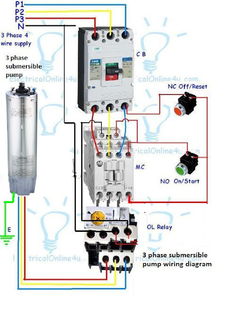
Today I am here to share with you the 3 phase submersible pump wiring diagram. In which I control a three phase submersible pump motor using magnetic contactor. Not only a contactor but also I install the thermal overload relay which will protect the motor form burning in case of over current flow to the circuit. In the diagram I showed the 3 Pole MCCB breaker, magnetic contactor , thermal overload protection relay, and normally open, normally close push button switches. 3 phase submersible pump motor and electric wiring connection. This will be the complete guide of controlling a three phase submersible pump motor using magnetic contactor.
3 Phase Submersible Pump Wiring Diagram Explanation Complete Guide
Before I explain the diagram. I want to write about the device and things in this circuit. In Circuit first we use the MCCB breaker. (Module Case Circuit Breaker)
We used a three pole MCCB circuit breaker in the diagram. This circuit breaker will control the all substances use in the c ircuit and we can switch on/off the electric power supply by using the three pole circuit breaker. In the diagram I did not control the neutral wire. However if you want to control the neutral (N) black wire then you must use the 4 pole circuit breaker.
The next thing which used in the circuit is the magnetic contactor. Basically a contactor is a type of relay which we can use for different works. However if you want to learn more about the magnetic contactor basic explanation then the below guide is for you.
Also read:
Whats Magnetic contactor and how its works?
How Wire and Install MCCB ?
The push button switches which used in the circuit is NC and NO switches. The normally open contacts switch will be use for starting the motor. And normally close contacts push button switch will be used for switch off the motor or load.
The next device which use in the below 3 phase submersible pump wiring diagram is a thermal overload relay. Which we use to protect or switch off the motor or load during over current flow. This device is available in different shapes and different values according load. In thermal overload protector we have move able ampere adjustable. From which we can setup the ampere or load level.
Now come to the wiring connection of three phase submersible pump. This wiring connection is too simple just like our old diagram. In which I showed the three phase motor controlled using contactor and overload relay. You can also read and see the diagram by using the below link.
How to wire 3 phase motor with contactor
Direct Online Starter wiring diagram
Three phase submersible Pump Wiring Diagram with direct online starter
First see the 3 phase submersible pump wiring diagram and after that I will explain each step of below connection diagram.
 |
| Three Phase Submersible Pump Wiring Diagram |
In the above diagram I showed the L1 L2 L3 and N wire incoming supply with red, yellow, blue and black. In which the red, yellow and blue for 3 phases and black color wire for neutral.
• The incoming supply goes to MCCB circuit breaker. I shown the three poles MCCB breaker which is for controlling the three phase power supply and you can switch ON/OFF by using the circuit breaker. Then neutral wire is direct and if you want to control the neutral wire then uses the 4 pole circuit breaker.
• In the above diagram I shown the magnetic contactor which I also explain, the magnetic contactor wired after the circuit breaker. Click here to learn about magnetic contactor.
• After condactor, they connection done between the contactor load main contacts and thermal overload relay main input terminals.
• Phase wire connections comes from the MCCB output terminals and connected to NC push button switch and then from the normally close switch, this connection goes to the magnetic auxiliary normally open contacts. And to the normally open switch. From the normally open switch wire will gees to the other side of normally open auxiliary contact and to the stater coil.
• The neutral wire connected to the normally close contact of thermal overload relay . And form the other side of thermal overload relay normally close contact wire goes to the other terminal of magnetic contactor coil.
• In last does the connection of 3 phase motor or three phase submersible pump to the thermal overload relay main terminals.
• Also do the earth wire connection to panel box and to the motor.
I hope now you will be understood, however if you have any question according the 3 phase submersible pump wiring diagram. You can ask your question according to the three phase submersible pump wiring diagram in the below comment section. One thing more the above diagram and text in only for information base and in case of wrong connection done or if we do any mistake by creating this post or diagram, and due any wrong connection done we will not be liable for any losses. For more read our privacy and policy.
No comments:
Post a Comment