Friday, March 31, 2017

Electrical cable Wiring Diagram Color code

In Electrical engineering, different wires have different color codes. This makes it easy to differentiate and identify each wire .In diagram the live wire has a different color from the neutral wire and the earth wire. It is also useful for separating the three phases for three phase connections. And most importantly, it is good for safety purpose. The properties of one wire could be different from the properties of another and misplacing connections could be fatal to personnel handling the connections. The color coding convention in Europe is different from that of the United States.

Wire Color Codes In Europe :

In Europe, the standard used is specified by the IEC (International Electrotechnical Commission). The wiring standard was initially published as IEC 60446 but in 2010, it was merged into IEC 60445.

electrical cable color code wire diagram in europe live phase neutral

 - For single phase wiring, the new European color code use

  •  Brown color for live cable,
  •  Blue color for neutral cable 
  • Striped green and yellow color for the earth/ground cable.
 - For three phase wires,

  • Brown color is used for line 1, 
  • Black color is used for line 2 
  • Grey color is used for line 3.
 The new European color code takes account of proper phase rotation. The new standard was adop ted to prevent people from confusing the protective earth wire with other electrical wires. It also protects people that have red-green color blindness.  In the old IEC color code, all lines in the three-phase supply were black or brown and that caused so much confusion.


The United Kingdom now use the new IEC color code format. The United Kingdom used its own color code till 2004. In March, 2004, the UK adopted the IEC color code.  

Electrical Cable Wiring in the United States :

There are two color codes available in the United States for different voltages. For 120/208/240 V single phase, the live cable is lack or red, the neutral cable is white colored while the protective earth can be green, bare or striped green and yellow in color.  For three phase 12 0/208/240 V, the first phase is colored black, the second phase is colored red while the third phase is colored blue.

electrical cable color code wire diagram in europe live phase neutral


For 277/480 V AC power, the neutral power is colored gray while the earth is colored green, bare and striped green and yellow. The phase 1 is colored brown, phase 2 is colored orange, the phase 3 is colored yellow. The 277/480 V AC systems are usually used for industrial equipment and motors.
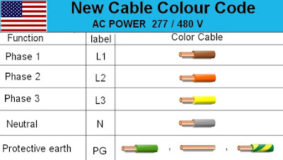


electrical cable color code wire diagram    usa live  neutral

Bottom Line

The color code convention for each region should be followed. It will prevent electrical shocks due to wrong identification and inappropriate connections. When you are faced with a tangle of wires and you need to do or repair some wiring, take note of the house electrical color coding wiring of that country.

The United Kingdom and Europe use the same color coding while the United States has its own color coding convention. Indicator lights on panel boxes usually use this sa me color coding convention. It must also be noted that older connections may use different color codes

Are You Interested in article :
  •  3 Way Switch Color Code
  •  4 way Switch Color Code 
  •  RJ45 Color Code
  •  Trailer Color Code
DIY Table Top Photo Studio Plans

Every so often I try to get rid of things I don't need any more by selling them on Ebay or Craigslist. I've found that having good photos helps items sell faster and get better prices so I made this little table top light box to take better product photos. It was made mostly of things I had lying around. Here are plans to build one yourself.
Read more »

Thursday, March 30, 2017

How to Wire Voltmeters For 3 Phase Voltage Measuring

In our last class you learned the method of wiring 3 phase voltage meter but that was only for just measuring the voltage between 2 phase or 2 line voltage. In this article you will learn complete method of 3 phase voltage measuring and its voltmeters wring. In this post i will show you that how to wire 2 voltmeters for three phase voltage measuring.

How to Wire Voltmeters for Three Phase

In this wiring diagram we use the two 3 phase volt meters which is wired between one another, my means that we wire one volt meter as we wired in our last post but we get a Line wire for 2nd voltage meter and then we connect the 3rd line or phase wire to the 2nd voltage meter to complete the electric circuit.
I know with out a diagram, its too difficult to make understand a body thats why i designed a diagram about this.

voltmeter wiring diagram

As i shown in the above diagram, i wired 2 volt meters for three phase power supply. I shown three phase supply Line wires with red, yellow, blue collars and black as neutral. As i shown, " connect the L1 to the first voltage meter and then connect the L2 to the first and 2nd voltage meter as i shown in above  diagram. In last connect the L3 to the 2nd terminal of second volt meter as i shown.


Message:

Note that this voltmeters 3 phase wiring diagram for analog voltmeters and INSHALLAH soon i will make a post about the digital voltmeter wiring diagrams for three phase.
This is request for our reader to share this website on social media. Thanks and if you have any question regarding this post then you can ask me in comments section.

3 Phase Submersible Pump Wiring Diagram with DOL Stater

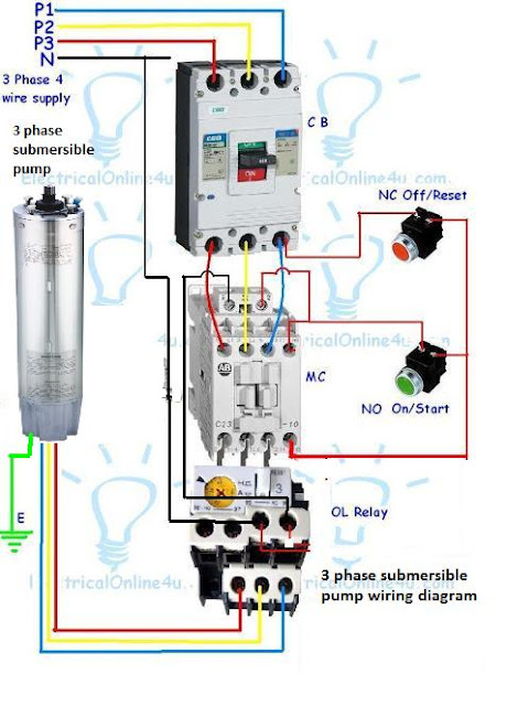
Today I am here to share with you the 3 phase submersible pump wiring diagram. In which I control a three phase submersible pump motor using magnetic contactor. Not only a contactor but also I install the thermal overload relay which will protect the motor form burning in case of over current flow to the circuit. In the diagram I showed the 3 Pole MCCB breaker, magnetic contactor , thermal overload protection relay, and normally open, normally close push button switches. 3 phase submersible pump motor and electric wiring connection. This will be the complete guide of controlling a three phase submersible pump motor using magnetic contactor.

3 Phase Submersible Pump Wiring Diagram Explanation Complete Guide


Before I explain the diagram. I want to write about the device and things in this circuit. In Circuit first we use the MCCB breaker. (Module Case Circuit Breaker)
We used a three pole MCCB circuit breaker in the diagram. This circuit breaker will control the all substances use in the c ircuit and we can switch on/off the electric power supply by using the three pole circuit breaker. In the diagram I did not control the neutral wire. However if you want to control the neutral (N) black wire then you must use the 4 pole circuit breaker.

The next thing which used in the circuit is the magnetic contactor. Basically a contactor is a type of relay which we can use for different works. However if you want to learn more about the magnetic contactor basic explanation then the below guide is for you.

Also read:
Whats Magnetic contactor and how its works?
How Wire and Install MCCB ?

The push button switches which used in the circuit is NC and NO switches. The normally open contacts switch will be use for starting the motor. And normally close contacts push button switch will be used for switch off the motor or load.

The next device which use in the below 3 phase submersible pump wiring diagram is a thermal overload relay. Which we use to protect or switch off the motor or load during over current flow. This device is available in different shapes and different values according load. In thermal overload protector we have move able ampere adjustable. From which we can setup the ampere or load level.


Now come to the wiring connection of three phase submersible pump. This wiring connection is too simple just like our old diagram. In which I showed the three phase motor controlled using contactor and overload relay. You can also read and see the diagram by using the below link.

How to wire 3 phase motor with contactor
Direct Online Starter wiring diagram

Three phase submersible Pump Wiring Diagram with direct online starter


First see the 3 phase submersible pump wiring diagram and after that I will explain each step of below connection diagram.


3 Phase Submersible Pump Wiring Diagram
Three Phase Submersible Pump Wiring Diagram


In the above diagram I showed the L1 L2 L3 and N wire incoming supply with red, yellow, blue and black. In which the red, yellow and blue for 3 phases and black color wire for neutral.


• The incoming supply goes to MCCB circuit breaker. I shown the three poles MCCB breaker which is for controlling the three phase power supply and you can switch ON/OFF by using the circuit breaker. Then neutral wire is direct and if you want to control the neutral wire then uses the 4 pole circuit breaker.
• In the above diagram I shown the magnetic contactor which I also explain, the magnetic contactor wired after the circuit breaker. Click here to learn about magnetic contactor.
• After condactor, they connection done between the contactor load main contacts and thermal overload relay main input terminals.
• Phase wire connections comes from the MCCB output terminals and connected to NC push button switch and then from the normally close switch, this connection goes to the magnetic auxiliary normally open contacts. And to the normally open switch. From the normally open switch wire will gees to the other side of normally open auxiliary contact and to the stater coil.
• The neutral wire connected to the normally close contact of thermal overload relay . And form the other side of thermal overload relay normally close contact wire goes to the other terminal of magnetic contactor coil.
• In last does the connection of 3 phase motor or three phase submersible pump to the thermal overload relay main terminals.
• Also do the earth wire connection to panel box and to the motor.

I hope now you will be understood, however if you have any question according the 3 phase submersible pump wiring diagram. You can ask your question according to the three phase submersible pump wiring diagram in the below comment section. One thing more the above diagram and text in only for information base and in case of wrong connection done or if we do any mistake by creating this post or diagram, and due any wrong connection done we will not be liable for any losses. For more read our privacy and policy.

Wednesday, March 29, 2017

What are Conductors and Insulators Guide

As you know that in your daily life you use two types of things, in which electricity or current flow is possible or in which current can flow easily and some are those material in which the current flow is impossible. These things we called conductors and insulators. For types of insulators and conductors we will deuces in last but the first is that what are conductors and what are insulators. I think the first thing is to know about that what the meaning conductor and insulator.

What are Conductors and Insulators?

Conductor

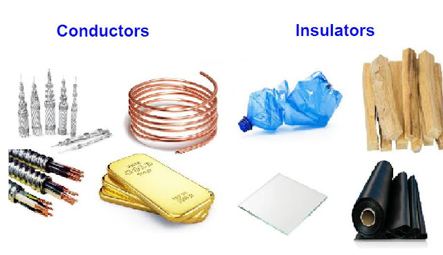
Those materials in which the flow electron flow is done easily, or we can said that conductors are those materials / things that permit a generous flow of electrons with very little external force (voltage) applied (book definition). In simple words conductor are those materials in whi ch the current flow possible or in which a electric current can flow easily.


Insulator

Insulator are those materials in which have very low number of free electron or in which the current flow is impossible or in which current can not flow is called insulator. In other words insulators are those things that have very few free electrons and require  large amount of applied voltage to establish a measurable current level (book definition) or the level of current from which a person can get electric current.

insulators and conductors


Types of Insulators and Conductors

A s i written in my about words that conductor are those materials in which current flow is done by applying a small voltage or power. However for better understanding i want to tell you same names of conductor.
Silver, Copper, Gold, Aluminum, Iron are good electrical conductors.


As i talk about that insulators are materials in which current or flow of electron impossible or in which the current can not flow easily, there are some types of insulators.
Glass, paper, Dried-Up wood, plastic, rubber are good insulators.
​​In Short we use mostly conductors and insulators for different use and there are many uses in of conductors and insulators and which can not ignore.


How Many Cables Can You Pull Through A Hole

A guide to help figure out how many cables you can pull through a hole to help you plan your structured wiring project.

I'd like to run new cables for TV, phone and network and I came up with this little chart that might help you figure out how many telecom cables you can pull through a hole. It includes Cat3 2-pair, Cat3 4-pair, Cat5 4-pair, Cat5e 4-pair, Cat6 4-pair, RG59 and RG6 Quad Shield in various sized holes.
Read more »

How To Wire An Electrical Outlet Wiring Diagram


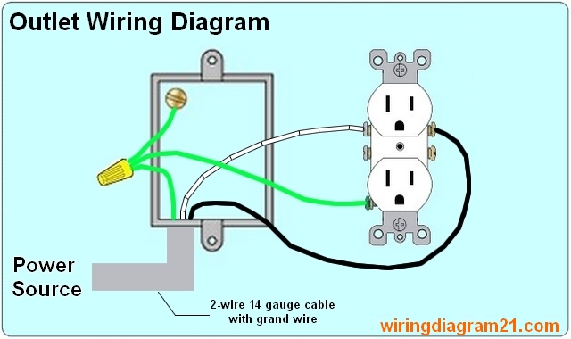
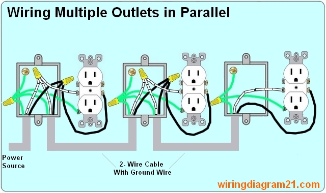
How to wire an electrical outlet / receptacle with wiring diagram Wiring an electrical outlet / receptacle is quite an easy job. If you are fixing more than one outlet, the wiring can be done in parallel or in series.

STEPS TO TAKE WHEN WIRING THE ELECTRICAL OUTLET/RECEPTACLE


how to wire Multiple electrical Outlet receptacle In Parallel serie  Wiring Diagram

How To Wire An Electrical Outlet :

  • Switch off the mains: You should switch off electrical power from the mains to avoid electrocution. One can’t be too careful. 
  • Run the cable from the circuit breaker to the location of the electrical outlet: Your cable should be long enough to reach each socket. The cable must also be strong enough to support the kind of load you want it to carry. 
  • Strip/peel off the cable before it enters the socket box: You can push in the cable to the box before screwing or nailing the box to the wall. Ensure the cable you feed in is long enough to reach the terminals of the socket. 
  • Connect the wires to the receptacles: The neutral, earth and live wire should be connected to the box. The earth wire is usually green/yellow while the live is usually pink/red. The neutral could be white or black. But these color schematics are subject to change depending on your country. The socket receptacles are usually marked with signs to indicate the position that each wire should go. 
  • Multiple outlets: To wire multiple outlets, follow the circuit diagrams posted in this article. 

Multiple Outlet In Serie Wiring Diagram :


For wiring in series, the terminal screws are the means for passing voltage from one receptacle to another. Any break or malfunction in one outlet will cause all the other outlets to fail.

how to wire Multiple Outlet In serie electrical Wiring Diagram


Multiple Outlet In Parallel Wiring Diagram :


When wiring receptacles in parallel, the wires are spliced to a pigtail that is connected to every outlet. The voltage at each outlet is not dependent on the other outlets.

how to wire Multiple Outlet In Parall   el electrical Wiring Diagram


Electrical Outlet with light fixture wiring diagram :


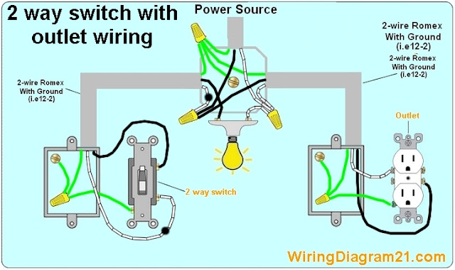
electrical outlet 2 way switch wiring diagram how to wire light with receptacl

NOTE :  white wires marked with a black circle are HOT not Neutral 

Electrical outlet with to way switch in switch box wire diagram:


2 way switch    with electrical outlet  wiring diagram how to wire outlet with light switch

Double outlet in one box wiring diagram :


double outlet box wiring diagram in the middle of a run in one box


Outlet controlled by switch in one box wire diagram :


wiring  outlets controlled 2 way switch  in one box diagram


Are You Interested in article :
  •   2 Way Switch Wiring Diagram
  •   3 Way Switch  Wiring Diagram
  •   RJ45 Wiring Diagram
  •   4 Way Switch Wiring Diagram

Tuesday, March 28, 2017

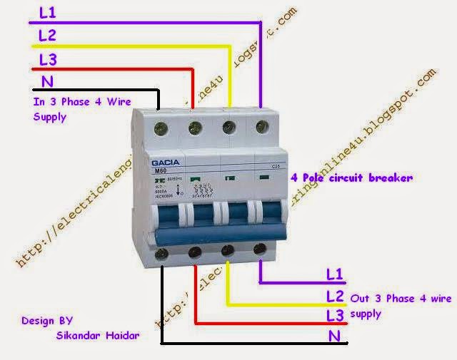
How to Wire 4 Pole Circuit Breaker For 3 Phase 4 Wire System

This post is about the complete wiring method of 3 phase 4 wire system wiring controlling through the 4 pole circuit breaker. In this post you will learn something about the Three phase four wire system controlling. Last time i published a post about the 3 pole breaker wiring if you did not read it then for better understanding read it.

3 Phase 4 Wire System Controlling From 4 Pole Circuit Breaker


Requirements :

As Supply : Three phase four wire
Breaker : four pole circuit breaker
Electric cables

Also read it :

Wiring of One Pole C Breaker
Wiring of Two Pole C Breaker
Wiring of Three Pole C Breaker

Method of controlling three phase four wire system through 4 pole breaker :


First of all switch of your in coming main line supply and after that connect the wires to breaker as shown in the below image. Just like below image / diagram connect the In voltage L1, L2, L3 and neutral to in terminals of breaker and then connect same the out connection wires as shown below.

3 phase wiring using 4 pole circuit breaker

In above image i use blue color line for phase 1, yellow for phase 2, red for phase 3 and black for neutral. Remember that we use only these colors for 3 phase wiring and if we have 110 or 220 voltage supply then we use black color wire for neutral and red for phase.

If you learn something from this blog then its will be your kindness to share this post with your friends, and always work carefully in electric wiring. Ad vance thanks for sharing.......


How to connect solar panel to battery With MPPT Solar Charge Controller Instillation

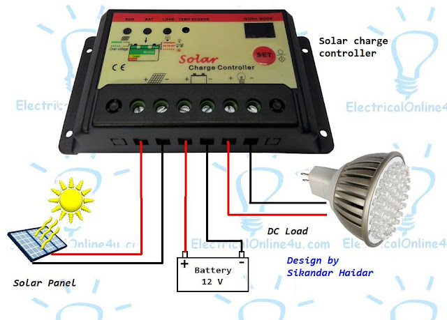
In my last post i written about the connection of solar cell to battery, in this post you learn about " how to connect solar panel to battery with MPPT (maximum power point tracking) solar charge controller. The post provide you the complete instillation of solar panel charge controller and battery  connection.


How To connect Solar Panel To Battery With Charge Controller?

The connection of solar panel to battery and installation of charge controller is too easy wiring connection but a new person is always want a guide to do this instillation. This too easy connection and which can be done by any one.
The complete method wiring solar panel to mppt charge controller and battery connection is too simple steps.

  • First of all connect the negative and positive wires of solar cell to charge controller solar panel negative and positive input terminals.
  • Then do connection between battery and charge controller.
  • The 3rd steps is not use too much however if you want use some DC (direct current) devices from the solar charge controller then get connect form solar charge controller for your dc load.
Note that in below diagram i shown the negative with black color and positive with red color lines.
All steps is incomplete before a diagram and note that above all steps do regarding the below solar charge controller diagram.
how to connect solar panel to batter and solar charge controller
Same follow the above me thod of wiring or to connect a solar to battery as i shown in above solar panel wiring diagram.
I hope after this diagram you will completely understood and you will be able to do the connection with out any person help.

Monday, March 27, 2017

12 Stocking Stuffers for the DIYer under 25

Twelve useful tools, gadgets and accessories under $25 that make great stocking (err... toolbelt?) stuffers for the DIYer in your life. What's great about most of these is even if they already own one, a second one to keep in another location will be very handy.
Read more »

Milwaukee Hackzall Review

Ive owned my Milwaukee M12 Cordless Hackzall since almost the beginning of 2013. Since then, Ive reached for the Hackzall more than any of my other saws and havent used my corded reciprocating saw at all this year.

Every time I use it Im blown away by how powerful this little cordless reciprocating saw is. Milwaukee has managed to squeeze a lot of power out of only a 12V Lithium-Ion battery.

Considering Jerome Schnettler and Edware Ristow invented the Sawzall (first reciprocating saw) back in 1952 for Milwaukee, its no big surprise that Milwaukee would come out with such an innovative new design. Although it has the same shoe , uses the same blades and can be used for the same types of cutting activity as a reciprocating saw, it is a whole new type of tool.

While other cordless reciprocating saws merely tack a battery pack onto the back of a standard looking reciprocating saw, Milwaukee took a different approach with the Hackzall creating a compact reciprocating saw that can be used in a lot more places.

The smaller size of the Hackzall opens up a lot of possibilities. Its easy to carry and use with one hand which makes it great for using in tough to reach spots or when on a ladder. It leaves one hand free to secure the work piece but at the same time theres enough room on the small body to grab it with both hands for greater control.

The variable speed trigger smoothly controls the speed of the blade from between 0 to 3,000 strokes per minute and a br ight LED illuminates the cut area. Four red LEDs next to the blade lock indicate how much charge is left in the battery. These LEDs are activated every time you pull the trigger so you dont forget to check.

A twist lock mechanism provides tool free blade changes of any blades that will fit in a standard reciprocating saw. The blade can also be mounted in reverse. With the blade facing the opposite direction you can get in some tighter spots since the shoe is shorter on the back end.

Overall the tool is built tough and can handle a lot of abuse. Ive used it for cutting 2x lumber, some metal pipes, bars and have used it extensively over the summer in the landscape to cut thicker branches that would have taken a long time to do by hand.

I dont know that Id grab it if I needed to demo a large area (nor would I use any cordless saw for that) but for the occasional cutting job throughout the day it works well. The Hackzall would be a great tool for plumber s, electricians, etc to in their tool bag whenever they need to cut through framing. Great saw for the homeowner that likes to tackle weekend projects but tough enough to withstand daily use too. Ive put the M12 batteries through some tough situations and theyve held up. Other Li-ion batteries for other tools Ive owned havent done as well through similar use.

If you already own other M12 tools you can purchase the bare Hackzall without a battery or charger. If you dont, you can purchase the Hackzall with battery and charger. If you need more power, a slightly larger 18V Hackzall is available that uses the M18 RedLithium batteries.

Sunday, March 26, 2017

How to Fix Refrigerator Compressor Not Running Problems

Today i am gonna to to guide you about how to fix refrigerator compressor not running problems, which we mostly face. This is a complete  guide of fixing fridge compressor not working or running problems. In this post i am writing about the common problems of refrigerator compressor and how to fix these compressor problems step by step with complete explanation.


Refrigerator Compressor Not Running Problems and How to Fix it


There are many problem which may case of Ref or fridge compressor stop working, but i try my best to cover some most common reason. We will highlight it step by step....

refrigerator compressor not running


Mostly compressor or fridge not working in case of no incoming power supply, for this issue first of all check your main distribution board to check breaker from which you get your supply for your refrigerator or for electrical outlet which is in used for your REF. If the breaker is in off or tip state then on it and if still it is trip again then check your supply line, may be a short circuit in your supply. Now if you switch on the breaker and breaker not tripping then check the outlet where your plug in the fridge plug, for testing the outlet (socket) the easiest method is that to plug in the plug of other electrical appliances (i.e example stand fan, set the knob of multi meter for testing AC voltage and insert the meter testing leads to the outlet.) Now if outlet have not receiving the power supply then change the outlet or fix th e outlet problem. For that call a professional and if you can do this him self then do it but carefully. Here some posts which help you about outlets connection.

Also read
How to wire Electrical Outlets?
How to identify compressor terminals?
8 Reason of refrigerator / fridge not cooling
What is PTC Relay and How its works?
What is working of Overload Protector?
How to check compressor winding?

Then next common problem of compressor not starting is that " your fridge supply wire will be cut internally", in this case your refrigerator all machinery will not work, the cooling fan, light etc. Note that in above electrical supply problem the refrigerator will same problem and other devices cooling fan , light etc will not working too.


The other common reason of compressor not running is that your fan internally light will be glowing but your compressor will not working, for that i suggest yo u test first of all the internally thermostat that refrigerator thermostat is working or not working, As you know that thermostat is connected in series with compressor and supply goes through the thermostat, now if thermostat is stop working and making a open connection then how can the electrical supply will run to compressor. For that fix the refrigerator thermostat or change it.

In some cases, some one or mostly children move the thermostat knob on switching off direction, so first of all chick the thermostat switch and if this on off direction then change the direction of thermostat knob. One thing more that we use thermostat switch for regulating the temperature and if your compressor start only for some time and before to make ice , compressor is switch off, so in this case your refrigerator thermostat switch is on low cooling , for that do setting of your refrigerator thermostat for high cooling.

Some time overload burn or cut due to high current flow, this happened when the supply off and again ON in some seconds, and the ptc relay can no start compressor again and compressor get high current and overload cut internally. (This happened because when compressor is running form the ptc internal heating resistor heated and make high level resistor shape between the run and starting terminal. As you know that ptc relay heating resistor provide a starting current form run terminal to start terminal for a small time and when its provide current to start terminal its heat up and due heat up the heating Resistor make high resistance and stop the current from run to start.)
So test thermal overload protector by using the multi meter and if thermal overload have connectivity between two points then your thermal overload is working and have no internal problem but if the thermal overload is internally open then change it. (Note that when thermal overload temperature is high its make an open circuit, so the best method is to cool the thermal overload protector and when its cool test it by using the multi meter.
    PTC Relay is the main part which start the fridge compressor, When ptc relay stop working the compressor also stop running. So if your PTC (positive temperature coefficient thermistor) relay is not working or burn then change with same type of relay.

    Capacitor is also one of the reason of  refrigerator compressor not running. Some time we use capacitor with capacitor start relay which make a strong starting current for starting compressor. There are two types of capacitor which we use with refrigerator compressor with relay which are starting capacitor and running capacitor. And if capacitor not working then change capacitor with same type of capacitor.

      Due To Low Voltage
      Voltage is also one of reason of  which make refrigerator compress or not running, so use a voltage regulator or voltage steplizer to provide the same ratio voltage which compressor need to start.

      I hope this article help you fix refrigerator compressor not running problems, however if you have still face any fridge compressor not running or working problem then you can ask in below comments section.

      How To Identify Refrigerator Compressor Terminals

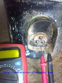
      In the refrigerator compressor we have three terminals but it is very hard to identify compressor terminals or find out that which one is start, run and common. In this article you will learn that how a person can easily find out the compressor terminals. For testing compressor terminals we use an ohm meter or any multimeter which have ohm testing option and i hope after reading this post we will completely understand and identification compressor terminals will no more problem for you.


      How To Identify Compressor Terminals


      We know that compressor have three terminals and in these terminals one is called (Start terminal) 2nd called (Run terminal) and 3rd called (Common terminal). But you dont know that which one is start, run and common.
      E.g : If you have refrigerator or Air conditioner compressor and you want to identify the terminals then follow the b elow method.

      First of all gave name to the terminals, for example you gave name to terminals A,B,C. Then set multimeter on Ohm. Put leds of multimeter and test the A and B terminal, then check the A and C terminals and then B and C. You will find high resistance between two terminals. For example you Find 50 resistance between A and B terminals (A-50-B), its means that these terminals are start and run and the 3rd one is common. So you find out the common terminal and now you want to identify the start and run terminal.

      So the resistance between common and start terminal will be higher from the resistance between common and run terminal. E.g if your resistance between C and B is 25 ohm and your resistance between C and A is 15 ohm, its means that your B terminal is start and your A terminal is Run.

      digit   al multimeter on ohm

      Final words :

      Use a high quality ohm meter to find out the start, run and common terminals.
      The resistance between start and run terminals will be high from start and common Or from run and common terminal.
      The resistance between Start and Common terminal will be high from the Run and Common terminal.

      refrigerator compressor terminals identification


      Message :

      I hope now you completely understood and you can easily identify compressor terminals, now if you have any question regarding this article then you can write your massage in below comments section.

      Saturday, March 25, 2017

      What is Earthing System and How Earth System Works for Protection

      In electrical technology and electrical maintenance work, the most important thing is protection and safety and earthing is one of them. In this post is about what is earthing system or grounding. As you know that In single phase and three phase wiring we have a wire which is green or green plus Yalow and which connection is with electrical machine body which is called earthing but why this is important and how its work. To clear these question from minds i am writing this post.
      As i told in my above words that protection and safety is important in every work and when we talk about those works which is related with electricity power, the dangerous is very big then other works. Every one now that electricity is danger and but in world if some thing is dangers and make problem but every one agree with this that every problem have a salutation. In electrical works we can not say 100 % that we can make people completely saf e form electrical shocks and accidents. But if we follow some protection roles and also do work with complete safety roles then we can stop these accidents  more then before.

      What is Earthing System or What is Grounding System

      Most electrical appliances, machines and motors body are made form the steel, these bodies are insulated to make safe but a Small mistake can case of big accidents. Due to this we face accidents in which many lost lives and money. The necessary is that to protect and safe him self form these accidents or do the right work which can stop these accidents. For that we do connection between electric machine steel body and earth by using a thick wire which is called earthing system.
      Or we can said that the connection between electric appliances steel body and earth is called earthing system.

      In this process a steel or copper plate is buried in ear th which we known with name of earthing plate and cooper wire is connected to the earthing plate. This wire connect to electrical machine body or frame to make a connection between machine body and earth. This is called earthing system or grounding system.

      Import acne Of Earth / Grounding System in our lives 

      All electrical machine or appliances insulated but if this insulation remove or hot or phase wire connect the machine body frame then some quantity of current live his right way and start flowing to the machine steel body which is called leakage current. In this case the workers which working on these machine can fell or get a big electric shock which may case of injuries or deaths.
      But if we make a link between electric machines body and earth then the electric current flow through the machine steel body to earth and the human life safe form electric shock. In this process the elec tric current flow to earth instead human body because the resistance of earth is low contest a human body. The electric current flow always select way in which have a low resistance. And we can safe him self form a Strong electric shock.


      How earthing system is working for protection of electric shock

      In earthing connection we make a link between electric machinery by electric wire (which we called earth wire) with earth. The connection of earthing is that we  connect the earth connection wire to the metal body of electric machine which we connect which connect to earth. The connection of earth and machine by using the a conductor or electric wire is called grounding or earthing.
      As you know that electron flow is called current and current always chose those way for flow which have low resistance.

      So what happen when we did not do the ground connection to electric ma chine. When we did not do this connection and in case machine have faulty or the phase (line wire) connect to the machine body or the the machine is internally short circuit. So the phase current always try to flow to ground and when some one touch the the metal body of this faulty machine , he fell a big electric shock and which may make case of a big injury or death. In this case the phase current use the human body as conductor and start flow from human body to the ground. If that person stand on insulator type of surface and have no link with earth then by touching this faulty machine nothing happened.
      So if we connect the a earth wire to the machine body then the phase current start flowing form metal body to the earth my earth wire.
      The resistance of earth wire is low from a human body and as i told in my above words that electricity or electric current always flow and chose those ways which have low resistance or in which the current flow can move easily,

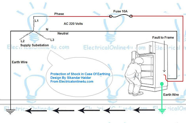
      Let take an example. In the below example diagram i shown protection of shock in case of earthing system.
      earthing system diagram


      In the above earthing system diagram i shown incoming supply from supply substation which 220 volts of Alternating current supply. So the neutral wire direct goes to the machine (refrigerator) and phase wire is connect to a 10 ampere fuse and form the fuse it is connected to to machine. The substation is an transformer which secondary connection is in star (Y connection) and on star point a earth wire is connect. So machine have a fault to frame and the phase current start flowing form the frame to earth and this curr ent goes to neutral point of substation through the earth and its make a strong short circuit which start the over current flow and due over current flow the fuse will be burn or melting.
      One thing more in case of instilling high ampere fuse or circuit breaker, or connecting machine to low quality earthing system the fuse will not melt and when a person tech the machine, the fell a small electric shock or earth leakage current but if the earthing system is too week or the earthing system is high resistance earth then this earthing system can not protect you form electric shock accidents.


      How to Wire a Dimmer Switch

      In Electrical wiring we wire dimmer switches for ceiling fans, in this post you will learn dimmer switch wiring  with complete explanation diagram. In our last published wiring diagram i published a post about ceiling fan wiring and with dimmer diagram. To day in this post i share with you a diagram which i find on a dimmer switch.
      Last Friday i wired a room in my village and when i am gonna to instill the dimmer switch, i find a wiring diagram on the dimmer switch which was designed my company not by me but its can help you, and today i am gonna to share this diagram with you.

      Dimmer Switch Wiring Diagram

      dimmer wiring diagram
      Dimmer switch wiring diagram

      In the above wiring diagram, two terminals of dimmer is shown in which one for input and second for out put. We wired a dimmer in series between electric supply and ceiling fan. So as shown in above diagram one wire goes to direct to the ceiling fan and the second wire go to the dimmer and then to fan.
      Note that a dimmer will connect in series between supply and fan. If you wire a dimmer and its not working then change your dimmer connection.

      Also Read

      How to wire a ceiling fan with dimmer
      Function of Capacitors in fans

      Message:

      Now if you have any question regarding dimmer switch wiring or diagram then do ask me in below comment section.

      Friday, March 24, 2017

      Wire a Room and Washroom in Home Wiring

      In home wiring we wire room, washroom. In this post i will show you that how you can wire a room and washroom. In this wiring i wired fuse, indicator, 2 ceiling fans, 3 bulbs, 3 plug socket. In this home wiring diagram, i controlled all room wiring from a fuse, two ceiling fans controlled by switches and dimmers and light bulbs by switches. In washroom i wired an outlet and a light bulb by switch in below diagram.

      Home Wiring Diagram - Room With Washroom Wiring


      In this type of room wiring, i start wiring form main supply in below diagram. First of all connect the neutral (N) wire to all plug sockets, ceiling roos, light holders and indicator. Then connect your phase (L) wire to fuse and then get connection form fuse to all substance as shown in below diagram.

         Home Wiring Diagram


      In above diagram i wired to ceiling fans, in home wiring we use ceiling roos for ceiling fan but i didnt shown the ceiling roos in diagram. Use the 7/29 copper cable wire for plug sockets supply and main board in room wiring and for other low ampere substance use 3/29 cable.

      Massage :

      After so hardworking i designed the above diagram and write this post and if you learn some thing from this post then its will be your kindness if you share this home wiring diagram with your friends on social media. Thanks for sharing......

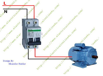
      How to wire Single Phase Motor From Two Pole Circuit Breaker

      In our last posts i share a post about how to wire a single phase motor. Single phase motor wiring connection learning is very important for electrical technology student and for every one. As i said that i already share a post about the one phase motor wiring but in my last diagram i wired the motor  with  one pole circuit breaker  but in this post we will learn that how to wire single phase motors with two pole circuit breaker. This wiring diagram and wiring connection is better then form first one because we control both wire or supply connection (neutral and phase) and we can switch both wire any time by using the 2 pole or 2 point circuit breaker.

      As we know that single phase motor is a capacitor start motor which can not be start with out a capacitor and its required a capacit or to start. You can also learn the function of capacitor by reading below post.

      Also Read

      Function of Capacitor in Fan or Single phase motor


      Wiring Diagram of Single phase motor with 2 pole circuit breaker

      To wire the capacitor start motor with two pole circuit breaker connect the AC incoming supply wires to the input terminals of circuit breaker and then connect the induction motor wiring connection or motor supply wires to output terminals or point of breaker as shown in below single phase motor wiring diagram.

      single phase motor wiring diagram

      Advantages of This single phase induction motor  wiring connection

      This is very safe and protected connection and we can disconnect or switch off the complete electric supply from motor.  This is one of the big reason of this connection that we can work any time with out any problem.

      Message

      I hope you learn from this single phase motor wiring diagram and now you will be able to wire you induction motor him self. Thank you for visiting……..

      Thursday, March 23, 2017

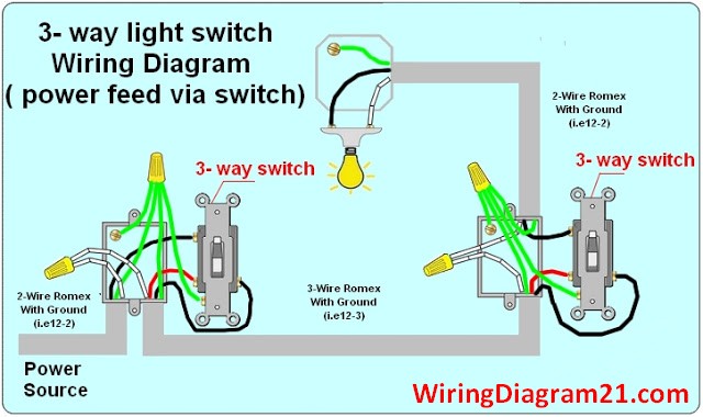
      3 Way Switch Wiring Diagram

      3 way light switch wiring diagram
      How to wire three way electrical circuit
      If you want to wire a three way switch you want to make sure that you are able to make sure that there is one light that is operated from two different switches. You need to make sure that both of these switches are a part of a 3-way switch, this happens when a standard switch will make or break a circuit and it means that there is a circuit which is either on or off. When there is a three-way switch, it is very important to make sure that the circuit is on or off, that means that you will have the wires routed to what are called the travelers. When you are able to work with these you will then allow the two switches to make contact through the same traveling wire and this is what is called a circuit. That means that you need to make sure that you are installing a new three-way switch, in a l ocation in which you have knowledge of the wiring, there is another hot wire that runs through the switch in this situation and you will need to know these details. If you are not sure you want to make sure that you are working with an electrician.

       Important Cautionary Note! You want to make sure that you are being safe and that means that you need to turn off the power to the circuit that you are working on. You want to make sure that you are working with a tester and that you also check this as well on your own.

      1.  3 Way Switch Wiring Diagram with Power Feed Via Switch :                                                                                                                                                                                          &n bsp;                                                    
        how to wire a 3 way light switch wiring diagram electrical circuit
                                                                           
                                                            You will see what you need to do when the power is coming to the light switch. The power source also connects the terminal main three-way switch and means that you need to have it spliced with a 3-way switch with the wire cable and that you will see the way that there is a neutral terminal with the light. When the hot is connected from the terminal to the hot of the light you will have completed this correctly.                                                    ;                                                                                                                                                                           
      2. A 3 Way Switch Wiring Diagram with Power Feed Via Light :

      how to wire a 3 way light switch wiring diagram electrical circuit

      You will see how it is possible to have the switches and the light when there is power that is coming into the fixture itself. That means that you want to make sure that you are able to wire the fixture that will connect to the light and also that it is going to be spliced through a light fixture. That means that the power will be able to be in the three-way s witch. You also want to make sure that you are able to see that the white wire is there and able to indicate that it is not being used as a neutral wire. You also want to know that all of the junction boxes are accessible. You also need to know that the chock block is completely enclosed and that it is possible for the ceiling not to be exposed to the heat of the lamp.

      Are You Interested in article :

      •  2 Way Switch Wiring Diagram 
      •  4 way Switch Wiring Diagram
      •  RJ45 wiring Diagram


      UBE Wi Fi Dimmer

      The UBE Dimmer is the first Wi-Fi enabled light dimmer that really gets it!

      I was looking around for home automation light controllers trying to find something that was wi-fi capable. Not a lot has changed since X10 first came about. There are new technologies but theyre all based on the same principles. Fairly proprietary systems that need proprietary controllers or services.

      Then I ran across this UBE Dimmer that is a true wi-fi appliance. It has a 32-bit ARM CPU and it runs Googles Android operating system with a full TCP-IP stack! If a ll those acronyms and terms are meaningless to you it means that the light switch is running a tiny computer in it that is as sophisticated as a smart phone.

      There will be apps for iPhone and Android that allow you to control individual lights, rooms, even set scenes for different occassions. From the video I saw they claim theyll have a public API that will allow anyone that knows how to write computer software to write their own custom software. You can even control your lights when youre away from home. Not having a way to directly access my wi-fi thermostat is the biggest gripe I have with it so this is very exciting!


      The dimmers also keep track of electricity usage. They can even tell you when a bulb needs to be replaced.

      And its not going to cost a fortune! You can pre-order the wi-fi dimmers from IndieGoGo where theyre trying to raise more money for the project. Theyve already received some funding and won a million dollar prize but they need more support.

      Theres a value dimmer that costs $49 that has a standard rocker switch and a premium dimmer that has a touch pad interface that will cost $69 but the first 500 people will get it for $59. Theres free shipping too. This is about the price of current remote control dimmers are going for now and they dont have nearly the same features and capabilities.

      In addition to the UBE Smart Dimmer there will also be a Smart Outlet and Smart Plug.

      Check them out at myube.co

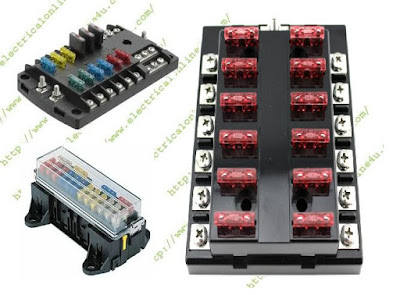
      Fuse Box Explanation and Advantages of Fuse Box in Electrical Wiring

      This post is all about the fuse box and importance in electrical wiring. In this post we will discus the electrical fuse boxes and its working and properties in electrical wiring. INSHALLAH our next post will about the fuses box wiring diagram. But in this post we will only lighting about the importance of fuses.

      What is Fuse Box?

      Fuse is electrical safety device which we use in electrical circuit to protect our electrical appliances from damages and burn. In simple words a fuse in an electrical low resistance device which protect the electrical devices form over current or to protect electrical wiring in case of short circuit.
      A fuse box is an electrical panel box where we wired all fuse for protection. Are we can said the circuit point where the fuses in connected between supply and circuit.
      Note That a fuse will always contact in series between supply and load.
      W e can also called circuit breaker box a type of F box, because the circuit breaker is also protection devices which we wire for safety in electrical wiring.

      fuse boxes


      How A fuse Works?

      A fuse is low resistance electrical device which cut off the electric current flow in case of high or over current flowing. E.g example if a fuse is design for 5 ampere (A) load and the circuit start getting high current (ampere). When current will increase  form the 5 ampere the resistance will heat of due to high current flow and due to heat the fuse burn and make an open circuit.

      Advantages of Fuse and Fuse Box

      There a lot of advantages of electrical fuse boxes , in which some are below.
      Fuse make our electrical wiring or circuit  protect.
      We can find out electrical short circuit from a circuit easily.
      We can test electrical wiring faults and problems easily.
      We can do electric work easily by switch off or plug out fuses from box.
      We can control all electric power using fuse panel box
      We can replace fuse easily in a small time. (Note that use those fuses which we can easily rewire or change).

      Wednesday, March 22, 2017

      How to wire Single Phase Kwh Energy Meter

      With another Electrical wiring class, I am gonna to publish a post about energy meter wiring diagram OR how to wire a single phase Kwh (Kilowatt Hour) energy meter. In this post i only share with you diagram in which i shown the complete method of energy meter wiring or instillation.

      Energy meter is an electric meter which read your consumption of current or load, In many places energy meter provide by electric supply company, and also its wired and instilled by electric supply company, however as electrical student you must learn this wiring connection but be safe before doing this or if you cant do this then call a professional.

      However my work to provide you the wiring diagram of kwh energy meter and its connection method. Below energy meter diagram i shown a single phase Kwh meter with incoming supply and out going supply to home, collage, shop etc.
      Kwh energy meter wiring diagram


      In the above diagram, i shown an utility pole form which i get supply to kilowatt hour E meter and after that i get supply form energy meter. In diagram i use red coler wire for Line ( phase) and black for Neutral wire.
      You can wire analog and digital energy meter using this method.
      But be Care full this is dangerous and always call a professional to do this wiring connection.

      How To Wire Ammeter For DC and AC Ampere Measurement

      In my last post i written about the ammeter and now this post is about ammeter wiring , In this post i will completer guide you about the ammeter wiring and its wiring diagram which i design for those student how can not learn from difficult diagrams.
      In this article we clear some most important question which make a problem for electrical student. I always try to tech student with advance and easy way.

      Also Read below
      what is ammeter or ampere meter and role of am meter

      How to Wire an Ammeter or Ampere meter

      We know that the flow of electron in electric circuit is called current and current is denoted by I and its unit is Ampere Which we denoted by "A". 
      Note ammeter wiring is always in series connection but this is only for low load, For high load measure or testing ampere we use the CT coil with ampere meter to measure the A.
      < div>In this article we talk about low load, and for low load we wire ammeter in series with circuit.
      In below diagram i shown that how to wire amp meter, in the diagram i shown two wire coolers in which one is Black and second is Red. You called this black and red cooler wires positive and negative for DC (Direct Current) or you can also called these coolers neutral and Phase for AC (Alternative Current).
      The DC and AC ammeter wiring method is same but for DC current you will use a DC ammeter and for AC current measurement we can only use the AC ampere meter.

      ammeter wiring diagram
      ammeter wiring diagram

      I hope now you will completely understood the ammeter wiring, In my incoming post i will share with you a diagram that how to wire ammeter for high load with CT coil which is also help you in power wiring or 3 Phase wiring.

      Tuesday, March 21, 2017

      How to Wire A 110 Block Telephone Connector

      110 wiring blocks are commonly used for distributing telephone lines in homes and offices. If your home was built after 1990 there's a good chance you have a 110 block connecting your telephone jacks to your incoming phone lines. They're a bit complicated but knowing how they work can wind up saving you a lot of money. In this post we'll go over over the different parts of a 110 block and how to wire your phone system.
      Read more »

      2 Way Light Switch Wiring Diagram

      This topic explains 2 way light switch wiring diagram and How to wire 2 way electrical circuit with multiple light and outlet  

      When you are looking to wire a two way switch there are easy ways to do it and complicated ways to do it. A two-way switch is one of the most basic parts of house wiring. You need to make sure that you understand the terminology and that you are completely comfortable with the lingo that is being discussed in the process. There are many configurations for wiring and making sure that you accomplish your goal. Many of the ways that you plan on how you are going to do it depend directly on where your power is located. We are going to look at how to wire a two-way switch.
              
      Caution :
      When you are ever working with electricity you need to make sure that you turn off the power before work is started. You want to know that it is completely off and dead. That means that you need to make sure that you are 100% sure that the power is turned off and that will let you know that you are ready to start

      • A 2 Way Switch Wiring Diagram with Power Feed from the Switch light :
      2 way light switch wiring diagram how to wire electrical circuit


      The power source comes from the fixture and then connects to the power terminal. You will see that there is a hot wire that is then spli ced through a switch and that then goes to the hot terminal of the light. It is very important to make sure that you have marked the wires as well so that it is clear what is neutral and what is not.

      •  A 2 Way Switch Wiring Diagram with Power Feed from the Light.
      2 way light switch wiring diagram electrical circuit schematic how to wire
      N OTE : the  white wire marked with a black circle are HOT not NEUTRAL

      The electricity comes from the source and then goes into the switch box that is spliced then from the light fixture. It is very hot and also connects to the switch to make sure that that it can be switched to the hot terminal portion of the light itself.

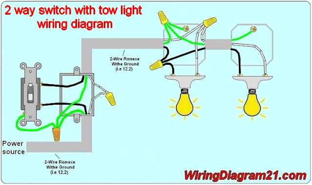
      2 way switch with multiple light wiring diagram :


      2 way light    switch wiring diagram electrical circuit schematic how to wire one switch tow light


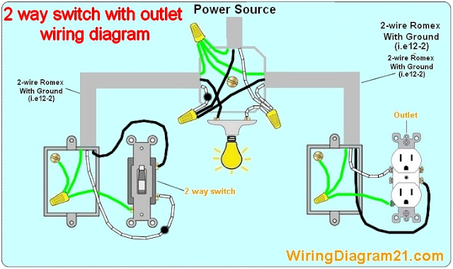
      2 way light switch with electrical outlet wiring diagram :


      2 way light switch wiring diagram electrical circuit schematic how to wire 2 way switch with outlet


       2 Way switch with electrical outlet  pour feed via light fixture :


      2 way light switch wiring diagram electrical circuit schematic how to wire

      NOTE : the  white wire marked with a black circle are HOT not NEUTRAL

      2 way switch wiring control ceiling fan :


      2 way switch ceiling fan wiring diagram and light fixture


      Are You Interested in a :

      •  3 Way Switch Wiring Diagram 
      •  4 way Switch Wiring Diagram
      •  Ethernet cable wiring Diagram
      •  How to wire an outlet 


      Monday, March 20, 2017

      How to Wire Bulbs in Parallel

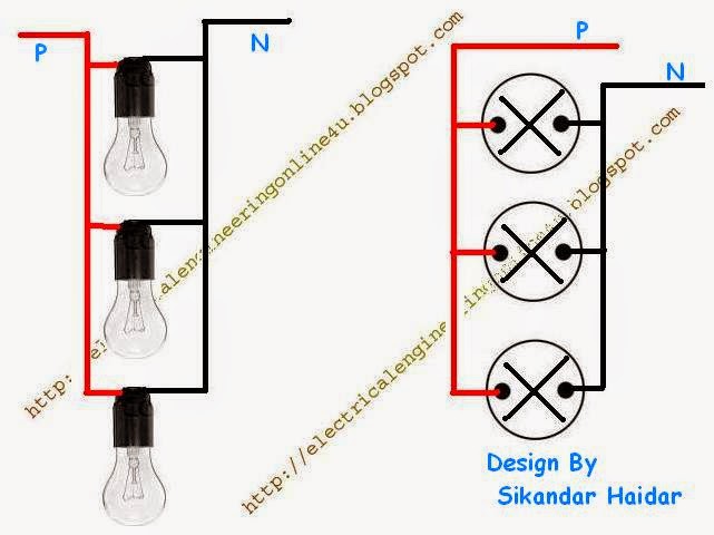
      Today you will learn about wiring lights in parallel with complete diagram, This type of wiring connection is used mostly in our daily life. In this parallel wiring diagram i shown three light bulbs with AC supply. Before i write about the diagram and wiring connection, " i want to write some about Parallel Circuit.

      How to Wire Bulbs in Parallel


      What is Parallel Circuit?

      A parallel circuit is a circuit which have two or more then two paths of flowing current, In this circuit the voltage (V) will be same in every path of circuit and Current (Ampere) will be different.


      Method of Wiring Bulbs in Parallel

      For wiring lights in parallel circuit, first of all connect Line wire (well known with name of Phase wire) to all bulb sockets / holders one one terminals as shown in below image / diagram and then connect the Neutral wire (N) to the others terminals of bulb sockets as shown in the below diagram.
      wiring lights in parallel diagram
      How to wire bulbs in parallel?

      In the about example diagram i explained the every part of this circuit with image and symbols, for better understanding i am gonna to share with a video tutorial, but before the video lets discus some advantage of parallel connection wiring.

      Advantages of Parallel Circuit.

      A parallel circuit have two or more then two paths of flowing current or completing circuit, e.g examp le if one of the about 3 bulb is fired or any other reason one bulb stop working then the two other bulb will continue the work which is best  for lighting system.
      In this circuit the voltage will be same in every point of circuit and ampere will be different.

      Video Tutorial 

      There are many advantages of parallel CKT, further i will write about this, however for better understanding i share a video tutorial below, watch it for better understanding and i hope after video tutorial you will completely understood the parallel and series circuit.


      Massage

      Now if you have any question regarding this post or wiring lights in parallel then do ask me in below comments section below. Keep visiting and advance thanks for supporting and sharing.

      How to Wire 3 Phase Motor with Circuit Breaker Contactor and Overload Relay

      We use three phase motor mostly in many places, in this post you will learn the 3 phase motor wiring with complete circuit breaker, contactor and overload relay diagram with step by step. We required some electrical things for three phase motor wiring which are below.

      Requirements

      3 phase induction motor
      3 core electric cable
      Three phase 4 wire system supply (three phase and one neutral)
      A circuit breaker
      A contactor or stater
      A overload relay
      and flexible wiring cable for cotactor coil and button wiring
      Normal close push button
      Normal open push button


      Before we starting talking about the wiring and wiring diagram, first we disuse the above substance . We required 3 core cable, a three core cable is a cable which have internal three electric cable which mostly in red, yallow and blue colors. The three phase 4 wire syste m supply means that we need 3 phase electric supply and one neutral wire. Note that we use the neutral wire for contactor coil wiring which we called the small wiring.
      We also required the circuit breaker which are 3 pole circuit breaker or circuit breaker which can cutoff the 3 electrical connection in same time.
      Normal close push button (NC) means that we need a push button which is normally have close electric circuit and when we push it then the button switch off the connection or change to the open electric circuit.
      Normal open push button mean that we need a push button which have a open electric circuit in normal state and when we push it then its change to the close electric circuit.

      3 Phase Induction Motor Wiring with Contactor Wiring Diagram

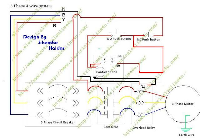
      To wire a 3 phase motor the first thing to wire is a circuit breaker which is disconnect and connecting point then we will get the supply form circuit breaker a nd connect supply to contactor or starter and then to overload relay. We connect the circuit breaker, contactor and overload relay in series between electrical supply and motor as shown in below diagram.

      3 phase motor wiring diagram
      power wiring

      Update Diagram For Direct Online starter So use the diagram.

      dol starter wiring diagram

      Contactor and overload Wiring


      In a contactor we have a magnetic coil which is use for switching. We have also NC and No point in a contactor which we can use for many connections. In overload relay we have an input and output points. In normally overload points have a close electric circuit between point but when ever the ampere or load is getting high the overload relay switch off or make an open electric circuit between these two point or connection. So we wire the overload relay in series between the cotactor coil current.
      So for contactor wiring first of all connect the neutral wire to contacto r coil first terminal and then connect a wire form the one output terminal of  circuit breaker which is opposite or phase current for contactor coil. In this process the small wiring which contactor wiring is also control by breaker and when we switch off the breaker, then  contactor will stop working auto.
      The small wiring wire which connect form the breaker output terminal will goes to the NC push button and then from NC push to the overload relay and NO push button as shown in above diagram. Then we connect a wire between the 2nd terminal of overload relay  and this wire goes to the NO point of contactor and then form NO point wire is goes to the 2nd terminal of contactor coil.
      Then in last we connect a were between NO push button switch and contactor 2nd terminal of coil where we connect the phase wire of contactor as shown in above diagram. And this wire connection is called tech current.


      Final wordNote that in all wiring use the best quality breaker, push button switches, contactor and overload relay. If your overload relay in not good then it will be not trip and if the overload relay does not trip or not switch the point then it will be case of your motor burn. Note that do all wiring control able from circuit breaker as i shown in above diagram.
      Note that always connect the earth wire to motor, and adjust the overload relay ampere by using the adjustment switch.


      Message

      I spend more then 2 hours on this article writing and designing diagram, so if you learn some important things then its your responsibility to share. Now if you have any question regarding the 3 phase motor wiring diagram then you can ask me in below comment section.